Electro-Thermal Coupling Simulation and Structural Optimization of Alloy Shunt Resistors under High-Current Conditions
I. Fundamental Pathways of Electro-Thermal Coupling
When a shunt resistor operates at its rated current, its internal temperature field is a direct consequence of the electric field. Joule heating (P=I2RP=I2R) is entirely converted into heat, and the thermal dissipation path is: resistor body surface → terminal electrodes and mounting surface → current-carrying busbar or PCB → environment. The temperature rise (ΔTΔT) dictates two distinct changes in resistance:
Resistivity Temperature Effect. The resistivity of the resistor body varies linearly with temperature, with the slope being the TCR. This effect is determined by the alloy system.
Thermal Expansion Geometric Effect. The length and cross-sectional area of the resistor body change with temperature. Thermal expansion along the length decreases resistance, while expansion in the cross-section increases it. In a flat structure, expansion along the length dominates. Consequently, the geometric effect and the temperature coefficient effect are in opposite directions and can partially cancel each other out—this is the fundamental physical basis enabling shunt resistors to achieve a low current coefficient.
Sampling Point Temperature Difference Effect. A distance always exists between the voltage sampling points and the heat-generating center, creating a temperature gradient. The resulting thermal EMF directly superimposes on the sampling signal. This effect is related to structural layout and is a designable parameter.
The net effect of these three superimposed factors is the current coefficient: the magnitude by which the shunt resistor's resistance increases with current after power is applied. For high-precision current sensing, the current coefficient must be treated on par with resistance tolerance.
II. The Correct Approach to Simulation Methodology
The value of electro-thermal coupling simulation does not lie in replacing physical testing, but in transforming structural trade-offs into quantifiable, comparable conclusions. A standardized modeling workflow consists of four stages:
Geometry and Mesh. The resistor body is a flat rectangular plate; current flows along the length, and the cross-sectional height is much smaller than the width. At the terminal electrodes, current concentrates and undergoes 2D diffusion. The mesh must be refined in the length, width, and thickness directions, with at least three layers in the thickness direction. Mesh independence verification is mandatory for review: after doubling the mesh density, the variation in center temperature and average temperature rise should be controlled within 1%.
Material Thermophysical Properties. Inputs require the resistivity-temperature relationship, thermal conductivity, specific heat, density, and coefficient of thermal expansion (CTE). Thermal conductivity decreases as temperature rises; in high-temperature regions, this causes the temperature rise to exceed linear extrapolation values—a common source of discrepancy between simulation and measurement.
Boundary Conditions. Heat dissipation methods determine the boundary conditions: natural convection versus forced air cooling, the equivalent heat sink of the current-carrying busbar, the thermal spreading capability of PCB copper foil, and the contact thermal resistance of the mounting surface. Engineering modeling must align with the customer's actual mounting conditions to match field data.
Electro-Thermal Coupling Iteration. First, solve the current field; then derive the temperature field from the dissipated power; then update the resistivity and iterate back to the current field until convergence. For uniform cross-section structures like shunts, a first-order approximation is sufficient for convergence, while second-order iteration verifies the reverse effect of temperature rise on current distribution.
The correct application of simulation conclusions is for screening: comparing the temperature rise and current coefficient of Structure A versus Structure B under given mounting conditions, eliminating inferior designs, and then subjecting the selected design to physical verification.
III. Four Controllable Variables in Structural Design
Sampling Point Location. The Kelvin (four-wire) connection separates the current path from the voltage sensing path. Placing the sampling points in the equipotential region at the center of the resistor body prevents sampling from being affected by the potential distribution in the current concentration zone. Milliohm's shunt series utilizes high-frequency welding technology, with screw hole designs that ensure precise sampling points based on this principle.
Flatness Ratio. A flat structure increases the current path length and reduces cross-sectional height, significantly lowering inductance: Milliohm's flat shunt design achieves inductance of less than 3 nH, performing exceptionally well at high frequencies. In high-current applications, inductance-induced sensing errors are on the same order of magnitude as thermal EMF errors, requiring joint consideration.
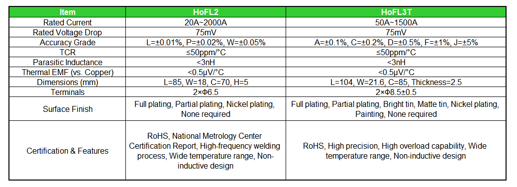
Mounting Surface and Hole Positions. The location and quantity of mounting holes determine the stress distribution on the current-carrying busbar and influence heat dissipation to the mounting surface. The hole dimensions specified in the datasheet (HoFL2: 2×Φ6.5 mm, HoFL3T: 2×Φ8.5±0.5 mm), along with length, width, and thickness, constitute the complete mounting geometry.
Surface Treatment and Plating Area. Surface treatment options—such as full plating, partial plating, nickel plating, bright tin, matte tin, and conformal coating—prioritize different properties regarding contact conductivity, solderability, and corrosion resistance. The plating area affects the bonding strength of the solder interface. Selection should be determined by the actual assembly process.
IV. Measured Specifications of Milliohm's Shunt Resistor Series
V. Measured Specifications of Milliohm's Shunt Resistor Series
The Milliohm shunt resistor datasheet provides a mechanism-level explanation for the current coefficient: specialized doping, fabrication, and heat treatment processes impart the shunt with a low current coefficient and favorable compensation characteristics. Because a specific distance inherently exists between the voltage sense points and the heat-generating center, a low thermal EMF is particularly critical—with the thermal EMF vs. copper maintained at <0.5 μV/°C. Furthermore, the planar structure of the shunt reduces parasitic inductance to <3 nH.
VI. Selection and Design Guidelines
1. Define the current rating first, followed by the structure. Select the appropriate series based on the combined requirements of rated current and rated voltage drop: HoFL2 covers 20A to 2000A, while HoFL3T covers 50A to 1500A. Both feature a nominal 75mV voltage drop but offer different accuracy grades, allowing for selection based on specific metering requirements.
2. Model based on actual mounting conditions. Provide the ambient temperature and thermal conditions (busbar dimensions, PCB copper area, forced air cooling, etc.). Our FAE team can calculate the usable power based on the derating curve and recommend a matching solution to ensure sufficient margin.
3. Incorporate the current coefficient and thermal EMF into the error budget. In wide-temperature and high-precision applications, the magnitude of their impact is on par with resistance tolerance; both must be evaluated alongside the error budget of the sensing circuit.
4. Ensure proper busbar interface matching. The connection interface between the shunt and the busbar must comply with the welding and anti-loosening requirements specified in the technical documentation, ensuring the current path and sensing path remain strictly independent.
5. Address range linearity in high-current applications. The proportion of millivolt-level sensing voltage decreases under low-current conditions; therefore, full-scale accuracy must be validated in conjunction with the system's dynamic range design.
Conclusion
Electro-thermal coupling integrates "structure" and "accuracy" into a unified engineering framework: temperature rise distribution dictates the current coefficient, sense point layout dictates the thermal EMF, and the flatness ratio dictates the parasitic inductance. The Milliohm shunt resistor series—featuring low current coefficient processes, a non-inductive structure of <3 nH, and a thermal EMF vs. copper of <0.5 μV/°C—covers a current range from 20A to 2000A and is supported by a State Grid Metrology Center certification report.
For measured current coefficient data, thermal simulation boundary conditions, or derating curves for specific models, please contact the Milliohm technical department for official specifications.
Failure Modes and Accelerated Life Modeling of Alloy Resistors under Combined Temperature Cycling and Damp Heat
Related Article