
Impact of Laser Trimming on Resistance Accuracy, Residual Stress, and Stability in Alloy Foil Resistors
I. Basic Principles of Trimming and Two Technical Routes
Resistance is proportional to the ratio of effective conductive cross-sectional area to length. The fundamental approach to trimming is to locally alter the current path, thereby raising the effective resistance into the target window. It is categorized into two routes by implementation:
Cutting Trimming. A kerf is created in the resistive layer via laser or mechanical means, forcing the current to bypass the cut. This is equivalent to lengthening the current path or narrowing the effective cross-section. The kerf geometry (width, depth, and orientation) directly dictates the resistance increment and final accuracy, making it well-suited for metal film and alloy foil resistors.
Trimming Line Route. In thin-film resistor structures, a dedicated trimming line is reserved, and fine resistance adjustment is achieved by removing or shorting this line. The structure of Milliohm's SMD MELF resistor HoCSRV incorporates a trimming line segment.
Trim Location Selection. The trim area should be positioned in regions of low current density, away from the main current path and termination electrodes, to minimize perturbation to the current and thermal distribution.
II. Laser Parameters and Resistance Accuracy
The accuracy of laser trimming is governed by two capabilities: resolution and controllability.
Energy and Pulse Width. Single-pulse energy determines the ablation volume scale. Excessively high energy density can induce microcracks and a recast layer at the kerf bottom, while lower energy density degrades the repeatability of ablation. In engineering practice, a low-energy, high-frequency cumulative approach is adopted, combined with in-line resistance measurement for closed-loop compensation.
Scan Speed and Overlap. Scan speed dictates the energy input per unit length, and overlap rate affects kerf continuity and wall roughness. The combination of speed and energy requires a balance between ablation efficiency and heat-affected zone (HAZ) control.
Focus and Spot Quality. Focal length and spot ellipticity determine kerf width consistency, which in turn affects the linearity of the resistance–kerf length relationship. Superior linearity accelerates closed-loop trimming convergence and reduces cycle time cost.
In-line Closed-Loop Control. Resistance is continuously monitored during trimming and processing halts immediately upon reaching the target window. This mechanism ensures unit-to-unit consistency, dictated by both trimming accuracy and measurement resolution.
Post-Trim Judgment and Margin. Accuracy specifications should distinguish between the trim target value and the factory acceptance value. An engineering margin is established between the two to mitigate edge-case failures in mass production statistics.
III. Correlation Between Residual Stress and Stability
Trimming induces a localized thermal process in the resistor body, with effects manifesting in three areas:
Microstructural Changes in the HAZ. Laser action causes rapid heating and cooling of the metal at the kerf edges, altering the microstructural state. Since the resistive layer of alloy foil resistors is an alloy material, these changes simultaneously affect local resistivity and temperature sensitivity, creating localized TCR variations.
Residual Stress Field. Shrinkage from rapid cooling is constrained by surrounding material, generating residual tensile stress on both sides of the kerf. During subsequent thermal cycling, residual stress superimposes on thermal expansion, initiating microcracks at the trim edges—the mechanism by which the trim zone becomes a fatigue-sensitive site.
Microcracks and Morphological Features. At excessively high energy density, a recast layer and microcracks may form at the kerf bottom. This affects the stability of the current path and provides a channel for moisture ingress in damp heat environments.
Quantitative Observation of Long-Term Stability. To evaluate the stability performance of the trimming process, resistance variation and visual inspection after the four test categories (temperature cycling, high-temperature storage, damp heat, and load life) should be used as the basis, with particular focus on comparing the differences between trimmed and untrimmed areas.
IV. Process Route Balancing Accuracy and Stability
Material and Structural Level. Selecting a resistive layer system with a small HAZ and low stress sensitivity is the fundamental route to mitigating trimming side effects. Milliohm's metal foil resistor HoJLR0603 directly lists "low thermal EMF, low inductance, and low TCR" among its product features.
Trimming Process Level. Adopt controlled-energy, narrow-HAZ processing methods, and control overlap and scanning strategy to avoid the recast layer. Follow trimming with stress relief treatment and protective layer passivation to seal microcrack channels.
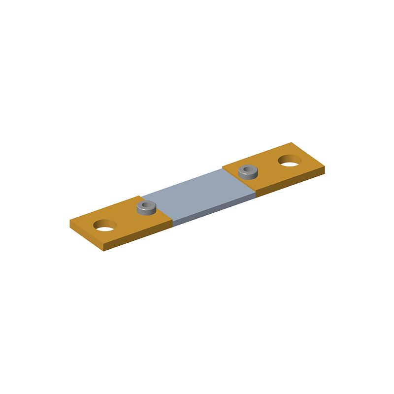
Verification Level. Once the trimming process window is established, closed-loop verification is completed with the full AEC-Q200 reliability test suite. Taking Milliohm's bare alloy resistor 2512 (HoLRS2512, 0.2 mΩ–5 mΩ, 3 W, −55°C to +170°C, max ±0.1% accuracy, TCR ±25 to ±100 ppm, inductance <3 nH) as an example of acceptance criteria:
| Test Item | Test Conditions | Acceptance Criteria |
| Short-Time Overload | 5x rated power, 5 s (JIS-C-5201) | ΔR ≤ ±0.5% |
| Temperature Cycling | 1000 cycles (−55°C to 155°C), 30 min dwell, 15°C/min ramp (TEST 4) | ΔR ≤ ±0.5%, no visual damage |
| High-Temperature Storage | 155°C, 1000 h, no load (TEST 3) | ΔR ≤ ±0.5% |
| Damp Heat | 1000 h, 85°C/85% RH, 10% rated power (TEST 7) | ΔR ≤ ±0.5% |
| Load Life | Rated current, Ta = 125°C, 100% power, 1000 h (TEST 8) | ΔR ≤ ±0.5% |
| Solder Heat Resistance / Solderability | Solder bath at 260 ± 5°C, 10 ± 1 s; Immersion at 245 ± 5°C, 3 ± 0.5 s | ΔR ≤ ±0.5%; Solder coverage ≥ 95% |
| Mechanical Shock / Vibration | 100 g half-sine, 0.5 ms / 10–2000 Hz, 3 axes (TEST 13/14) | ΔR ≤ ±0.5% |
V. Milliohm's Trimming Practice and Selection Guidelines
Milliohm has established clear engineering specifications for trimming and fine-tuning processes. Taking the bare alloy resistor series as an example, the datasheet outlines the trimming notch in its dimension table: The trimming notch is designed to adjust product accuracy without affecting other performance parameters. For products where the inherent accuracy meets requirements, no notch adjustment is required. This specification implies two key points: firstly, a dedicated process path exists for accuracy adjustment; secondly, the process is applied based on actual precision requirements rather than as a standard, universal step.
Selection Guidelines:
1. Determine the trimming magnitude based on accuracy requirements. If the inherent process accuracy meets the specification, additional trimming is bypassed. This not only streamlines the workflow but also preserves the physical integrity of the component.
2. Configure accuracy and TCR concurrently. High-accuracy grades and low-TCR grades represent a trade-off within the same process window. TCR should be prioritized based on the operating temperature span, followed by the allocation of the accuracy budget. Milliohm's product series cover the full spectrum from ±5 ppm to ±100 ppm.
3. Evaluate reliability criteria associated with trimming. For models involving the trimming process, verify the test conditions and acceptance criteria for temperature cycling, damp heat, and load life. Results obtained under different conditions are not directly comparable.
4. For high-volume production, focus on distribution rather than single units. Trimming accuracy is reflected in the spread and centering of the within-batch distribution, which should be evaluated using statistical analysis and CPK metrics. Once actual operating conditions are provided, our FAE team can calculate the usable power based on the derating curve and recommend the optimal package and accuracy grade.
Conclusion
Trimming represents the equilibrium between accuracy and stability: accuracy is achieved through controlled localized ablation, while stability is guaranteed by HAZ (Heat-Affected Zone) control and subsequent verification. Through its proprietary trimming notch design, thin-film trimming line structure, and a comprehensive AEC-Q200 reliability test system, Milliohm delivers dual assurance for precision realization and long-term stability, maintaining consistent performance across bare alloy, metal foil, and SMD MELF series.
For accuracy data related to trimming, reliability test reports, or derating curves for specific models, please contact the Milliohm technical department for official specifications.
Failure Modes and Accelerated Life Modeling of Alloy Resistors under Combined Temperature Cycling and Damp Heat
Effect of Heat Treatment on TCR and Long-Term Resistance Stability of Manganin Alloy Resistors
Related Article