Current Transformer vs. Shunt: Principle Analysis and Core Differences
I. Core: Principle Breakdown of the Two Devices
To understand the application differences between current transformers and shunts, it is essential to first clarify their core working principles — as these are the fundamental factors that determine their suitable scenarios and measurement characteristics.


① Current Transformer: A "current converter" based on electromagnetic induction
The working principle of a current transformer (CT) is fully based on the law of electromagnetic induction. Its structure typically consists of a closed magnetic core and two windings wrapped around it: a primary winding and a secondary winding. The primary winding has very few turns (usually only 1–2 turns) and is connected in series with the circuit to be measured, directly carrying the large current of the measured circuit. The secondary winding has a larger number of turns, with one end connected to a load such as a measuring instrument or a protection relay.

As shown in the figure above, when the current in the measured circuit passes through the primary winding N1, it generates an alternating magnetic flux in the core. According to the law of electromagnetic induction, this alternating flux induces a corresponding secondary current in the secondary winding N2. The core function of a current transformer is to convert the large current on the primary side into a small current on the secondary side (typically 1A or 5A) at a fixed ratio. The large current on the primary side can then be indirectly calculated by measuring the small current on the secondary side.
It is important to note that during operation, the secondary side of a current transformer must never be left open. If open-circuited, the induced voltage on the secondary side will rise sharply, which may not only damage the measuring instruments but also pose a serious safety hazard to personnel. This characteristic determines the special requirements for its installation and use.
② Shunt: A "voltage conversion expert" based on Ohm's law
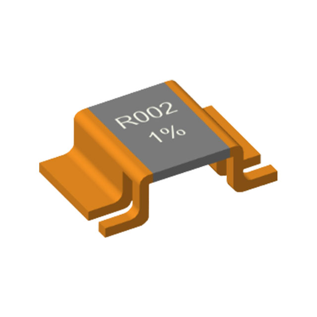
The working principle of a shunt is relatively more straightforward, with its core relying on Ohm's law. Essentially, a shunt is a fixed resistor with precise resistance and an extremely low temperature coefficient, connected in series in the circuit under test. When current passes through the shunt, according to Ohm's law (U = I × R), a voltage drop U is generated across the shunt, which is proportional to the current passing through it.

As shown in the above figure, by simply measuring this small voltage drop U and combining it with the known precise resistance value R of the shunt, the current in the circuit can be calculated using I = U/R. In simple terms, the core logic of a shunt is to "convert a current signal into a voltage signal," thereby indirectly measuring current by measuring voltage.
Since the shunt is fundamentally a resistive component, its measurement accuracy directly depends on the stability of its resistance value and the accuracy of the voltage measurement. Therefore, high-quality shunts are typically made of materials with very low temperature coefficients, such as manganin or constantan, to minimize the effect of temperature changes on the resistance value and ensure measurement accuracy.
II. Core Difference Comparison: A Comprehensive Review from Application Perspectives
Based on the different working principles described above, current transformers and shunts exhibit significant differences across multiple application dimensions, including measurement range, accuracy characteristics, applicable scenarios, installation and maintenance, etc. The following table and detailed explanations illustrate these differences:

III.Summary of Key Differences: Core Logic for Scenario Matching
From the comparison above, it can be seen that the core advantage of a current transformer lies in isolated measurement for high AC current scenarios. In contrast, the shunt features AC/DC compatibility, high accuracy, low cost, compact size, and easy maintenance — making it suitable for a much wider range of applications. The selection logic between the two is not about which is better or worse, but rather which matches the specific scenario. However, for most general-purpose applications, the shunt clearly offers superior overall suitability.
If you would like to learn more about our products, solutions, or applications in specific scenarios, please feel free to contact technical support.
Rated Power and Maximum Power for Shunts: In-Depth Analysis of Key Determining Factors
Application Analysis and Selection Guide for Alloy Resistors in Precision Equipment
Related Article