FL2 vs FL3T Shunt: Key Feature Differences
author: Milliohm Electronics
2026-03-13
I. Electrical Parameters
| Series | Rated Current | Voltage Drop | Tolerance | T.C.R(ppm/℃) |
| HoFL2 | 300A | 75mV | 0.1%~5% | ≤50 |
| HoFL3 | 300A | 75mV | 0.1%~5% | ≤50 |
II. Material and Structure Comparison
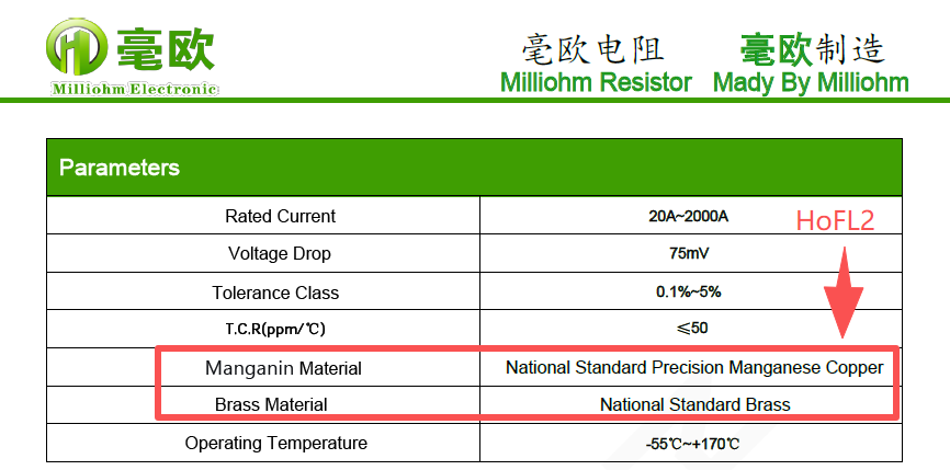
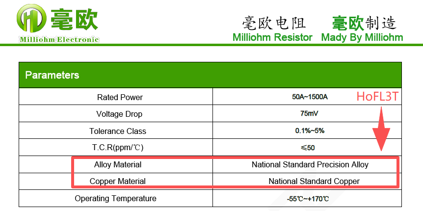
① Material Comparison :
FL2 series products: The electrode material is national standard brass, and the resistive element is national standard precision manganese copper;
FL3 series products: The electrode material is national standard copper, and the resistive element is national standard precision alloy.
FL3 series products: The electrode material is national standard copper, and the resistive element is national standard precision alloy.
② Welding Process
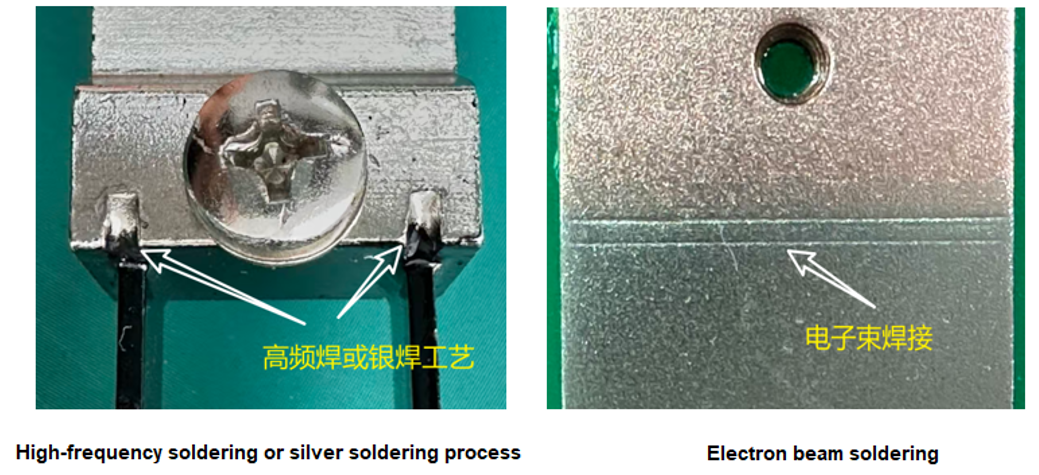
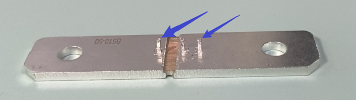
The welding process between the FL2 electrode and the resistive element is conventional high-frequency soldering, as shown in Figure 1 (left);
The welding process between the FL3T electrode and the resistive element is electron beam soldering, as shown in Figure 1 (right).
③ Comparison of Sampling Methods
The FL2 sampling point is commonly installed using screws.
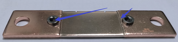
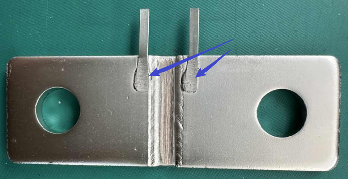
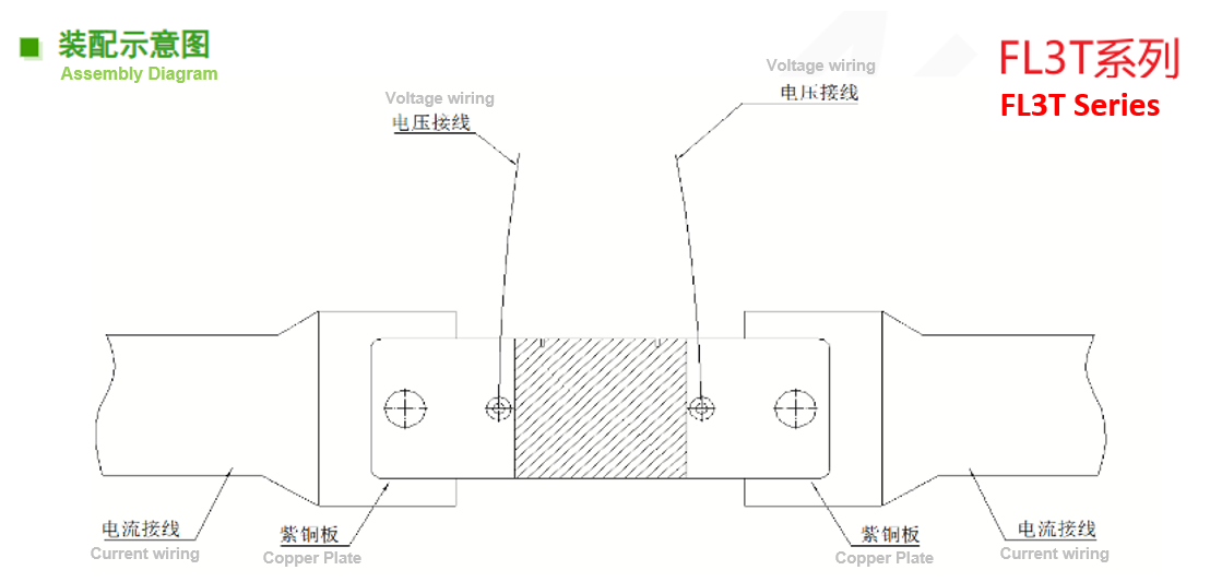
The FL3T sampling methods commonly include pin-type, crimp-type, and solder-type (as shown in the image below, pin-type, crimp-type, and solder-type, respectively). Additionally, the FL3T can be mounted on a PCB sampling module, facilitating improved product integration. It can also be used with a high thermal conductivity substrate or heat dissipation material to reduce temperature rise and its impact on accuracy.
The FL3T sampling methods commonly include pin-type, crimp-type, and solder-type (as shown in the image below, pin-type, crimp-type, and solder-type, respectively). Additionally, the FL3T can be mounted on a PCB sampling module, facilitating improved product integration. It can also be used with a high thermal conductivity substrate or heat dissipation material to reduce temperature rise and its impact on accuracy.
④ Package Size Comparison
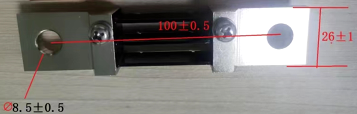
⑤ Comparison of Installation Methods
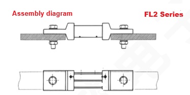
FL2 Package type: Fixed installation, Mostly in busbar form;
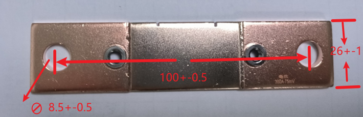
FL3 package type: fixed installation, the same installation method as FL2 and compatible with FL2 mounting dimensions. (Note: There are directional requirements for installation; the wire terminals must be on the crimp nut side.)
III. Summary
Based on a comparison of the electrical parameters, package size, manufacturing process, and materials of FL2 and FL3T, the following conclusions are drawn:
① FL3T has advantages over FL2 in welding process, mainly due to the more orderly molecular structure arrangement, less heat generation, and lower temperature rise in electron beam welding, resulting in better performance in terms of workpiece thermal stress and micro-deformation;
② FL3T electrodes use national standard purple copper material, which has better heat dissipation than the brass electrodes used in FL2;
③ FL3T has a smaller volume (using less material) than FL2 for the same power, resulting in lower cost.
④ FL3T has a simpler package structure, resulting in lower parasitic inductance and better performance in high-frequency and AC applications.
The FL3 has advantages in terms of product performance, quality, temperature, and cost.
HoFL2 Series purchasing link : HoFL3T Series purchasing link :

Analysis of Gold Aluminum Housing Resistor Products
Understanding Sampling Resistors in One Article
Related Article
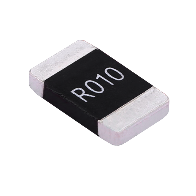
Key performance features: high power handling, ultra-low temperature drift, high overload withstand capability, low inductance at high frequency, and automotive-grade high reliability.
HoCG4527 Automotive Grade Molded Alloy Resistor
Key features: ultra-high current-carrying capability, ultra-high stability, ultra-low temperature drift, and low inductance at high frequency.
HoCG2728 Automotive Grade Molded Alloy Resistor

Alloy resistors, with their unique technical advantages—ultra-low resistance, low temperature drift, high power handling, low parasitic parameters, and strong pulse withstand capability—have become core components in current sensing, overload protection, and load matching circuits for EV charging stations.
Alloy Resistor Applications in New Energy