Core Discrepancies Between Exposed Alloy Resistors and Encapsulated Alloy Resistors
I. Core Structural & Manufacturing Process Differences
① Exposed Alloy Resistors — Structure & Process
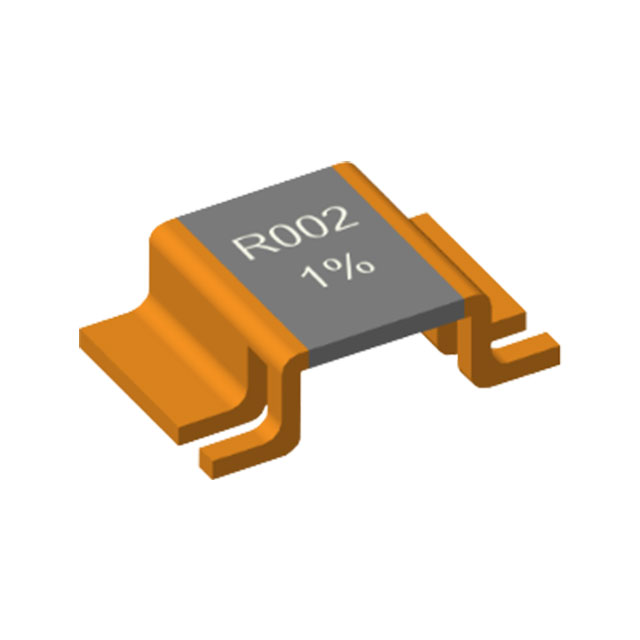
Bare alloy resistors, also referred to as open-frame alloy resistors or non-encapsulated alloy resistors, feature a core structure consisting of a direct-formed pure alloy substrate with no plastic, resin, or insulating adhesive coating. The manufacturing process is straightforward: precision alloy sheets are processed via stamping, etching, and bending to achieve the target resistance value, with metal terminals directly affixed to both ends. The entire resistor body remains fully exposed, in direct contact with air and the PCB environment.
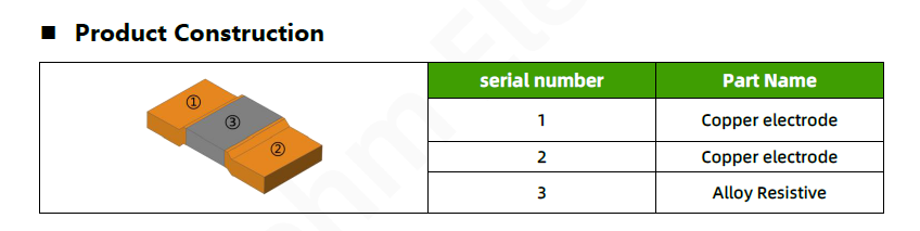
Common high-power sensing resistors in the industry—such as "U-shaped" and "flat-chip" types—fall under the category of bare alloy resistors. The overall structure features no additional coating or encapsulating medium. With high-purity substrate material and excellent resistance uniformity, the manufacturing process involves fewer steps and eliminates parameter deviations caused by molding or curing processes. As a result, bare alloy resistors inherently offer superior native precision and TCR performance.
② Encapsulated Alloy Resistors — Structure & Process
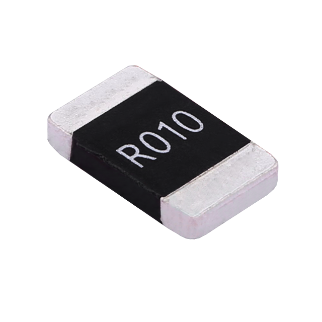
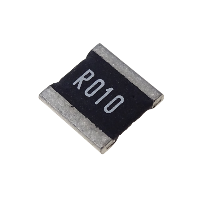
Molded alloy resistors feature a composite construction consisting of an alloy substrate with an insulating plastic overmolding layer. After the resistor element is formed and the electrodes are attached, the device undergoes high-temperature injection molding, resin encapsulation, or insulating coating processes to enclose the body in a black flame-retardant plastic or epoxy protective layer. Only the termination electrodes at both ends remain exposed, while the entire resistive core is fully sealed and protected.
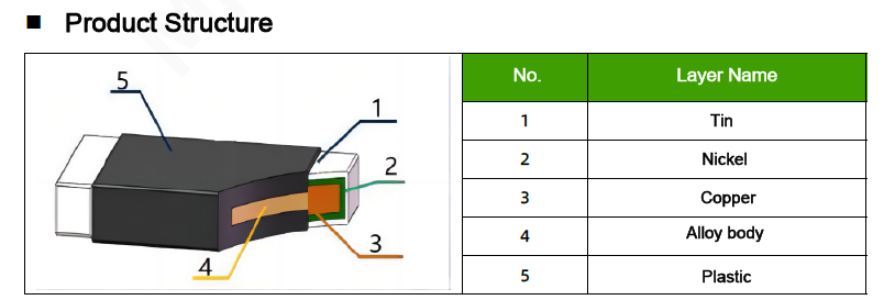
Molded packaging is the industry-standard encapsulation method for alloy resistors, compatible with standard SMD case sizes such as 1206, 2512, 2725, and 3920, covering a power range of 1W to 5W. The molded layer provides basic insulation, dust protection, and oxidation resistance. However, it also introduces a thermal insulating medium between the resistive element and the ambient environment, which structurally alters the resistor's heat dissipation and temperature response characteristics.
③ Summary of Key Structural & Process Differences
Exposed Alloy Resistors : Uncoated, pure alloy body, minimalistic structure, low process-induced losses, high parameter consistency.
Encapsulated Alloy Resistors : Insulating encapsulation layer, composite construction, mature manufacturing process, robust environmental protection, high degree of standardization.
These structural differences are the root cause of all performance divergences between the two resistor types.
II. Thermal Dissipation & Power Handling Capability — The Core Differentiator
① Exposed Alloy Resistor — Thermal Dissipation Characteristics
The most significant advantage of the bare structure is the absence of any insulating or thermal barrier, enabling full-surface direct air convection cooling. Heat generated during operation is rapidly dissipated from the exposed alloy body surface directly into the surrounding air, offering high thermal transfer efficiency, low thermal inertia, and fast cool-down response. Under transient high-current surges or short-term peak power loading, heat is quickly released, minimizing the risk of heat accumulation or localized hot-spot overheating.
Additionally, bare alloy resistors can leverage large-area PCB copper pour for auxiliary heat sinking. The direct contact with copper-clad regions allows efficient heat extraction from the substrate, further enhancing power handling capability. At equivalent package sizes, bare alloy resistors deliver significantly higher actual continuous power ratings and pulsed power withstand capability compared to molded types, making them the preferred choice for high-current and high-pulse applications.
② Encapsulated Alloy Resistors — Thermal Dissipation Characteristics
The molding compound — typically an insulating resin or plastic — exhibits very low thermal conductivity and acts as a thermal barrier between the resistive element and the ambient environment. Heat generated during operation cannot dissipate directly; it must first penetrate the mold layer before reaching the air, introducing a significant thermal resistance bottleneck that substantially reduces overall cooling efficiency.
Under continuous operation or prolonged power loading, heat tends to accumulate within the mold layer, causing the resistor body temperature to rise progressively. This leads to increased TCR drift and resistance value shift. Moreover, molding materials have limited high-temperature tolerance; prolonged exposure to elevated temperatures can cause aging, cracking, or delamination, further degrading heat dissipation performance. At equivalent volumes, molded alloy resistors exhibit lower rated power and pulsed power withstand capability compared to bare types.
③ Power & Thermal Comparison — Summary
| Performance | Exposed Alloy Resistor | Encapsulated Alloy Resistors |
| Heat Dissipation | Excellent; direct air convection, low thermal resistance | Restricted; heat must penetrate mold layer, high thermal resistance |
| Pulse Withstand | Strong; fast heat release, minimal hot-spot risk | Weak; heat accumulation, prone to drift and thermal stress |
| Power Capability | High; supports high current and peak loads | Limited; suited for steady-state moderate loads |
| Application Fit | Dynamic high-current / high-pulse scenarios | Steady moderate-power / smooth current scenarios |
III. Electrical Performance Differences — Precision, TCR, Resistance Range & Stability
① Precision & TCR Performance
Bare alloy resistors are free from mold-layer curing stress and thermal expansion/contraction interference from packaging materials. With the alloy substrate maintaining its intrinsic properties, they achieve extremely low TCR — typically ±25ppm/℃ or ±50ppm/℃, with high-precision grades reaching ≤ ±10ppm/℃. Tolerance classes cover ±0.01% to ±1%. Resistance drift under temperature variation is minimal, delivering exceptional accuracy in current sensing and voltage detection — ideal for precision measurement and control circuits.
Molded alloy resistors, on the other hand, are affected by thermal stress from the mold compound and CTE (Coefficient of Thermal Expansion) mismatch between materials, resulting in higher temperature drift. Typical TCR ranges from ±50ppm/℃ to ±100ppm/℃, with high-precision grades falling short of bare types. Moreover, after prolonged temperature cycling, stress relaxation within the mold layer can cause slight resistance shifts, making long-term precision stability comparatively inferior.
② Resistance Range Characteristics
Bare alloy resistors are specifically designed for ultra-low resistance sensing applications, with typical resistance values ranging from 0.1mΩ to 50mΩ. They are the preferred choice for high-current, low-voltage-drop sensing where minimal internal resistance preserves power loss and ensures high sensing sensitivity.
Molded alloy resistors offer a broader resistance range, covering both low and medium resistance values — typically from 1mΩ to 500mΩ — making them suitable for more general-purpose circuit applications. However, in the ultra-low resistance range (below 1mΩ), they cannot match the precision and consistency of bare alloy resistors.
③ High-Frequency & Long-Term Stability
Bare alloy resistors, with no packaging dielectric, exhibit minimal distributed capacitance and series inductance, resulting in excellent high-frequency characteristics and fast signal response — well-suited for high-frequency switching power supplies and high-speed sensing circuits. Additionally, free from mold material aging issues, they show minimal annual resistance drift under long-term operation and temperature cycling, offering superior long-term stability.
Molded alloy resistors, due to their external packaging, exhibit minor parasitic parameters that compromise high-frequency response. Moreover, mold resins gradually age and degrade under prolonged high-temperature or humid conditions, leading to internal stress changes and slow resistance drift. This results in more pronounced accuracy degradation over extended use.
IV. Environmental Adaptability & Protection Capability
① Bare Alloy Resistor — Protection Limitations
With no protective coating, the bare structure leaves the resistor body fully exposed, resulting in limited environmental robustness. In environments with high dust, high humidity, corrosive gases, or condensation, the alloy surface is vulnerable to oxidation, dust accumulation, and moisture ingress, potentially leading to resistance drift and poor contact due to electrode oxidation. Additionally, the exposed metal body poses a short-circuit risk, requiring adequate clearance spacing in PCB layout to prevent neighboring components from touching. Therefore, bare alloy resistors are best suited for sealed, clean, and dry internal equipment environments.
② Molded Alloy Resistor — Protection Advantages
The outer flame-retardant mold layer provides comprehensive protection — dust resistance, moisture resistance, oxidation resistance, corrosion resistance, and electrical insulation — effectively shielding the resistive element from water vapor, dust, and corrosive media. The molding materials, typically rated flame-retardant and heat-resistant, offer good tolerance to workshop dust, ambient humidity, and light oil contamination, making them well-suited for open or semi-open equipment environments.
Furthermore, the insulating properties of the mold layer eliminate short-circuit risks between adjacent components, offering higher PCB layout tolerance and wider environmental applicability. They perform reliably in outdoor equipment, industrial controls, and standard automotive applications.
V. Application Targeting — Clear Distinction
① Bare Alloy Resistor — Recommended Applications
①-1: Precision high-current sensing: Lithium battery protection boards, EV battery BMS, chargers, inverter current detection
①-2: High-frequency/high-speed circuits: High-frequency switching power supplies, servo drives, variable frequency control systems
①-3: Short-term high-pulse conditions: Motor startup, transient current limiting, dynamic load circuits
①-4: Inside sealed, clean equipment: Notebook power supplies, built-in power for smart home devices, compact industrial modules
② Molded Alloy Resistor — Recommended Applications
②-1: Open or harsh environment equipment: Outdoor power supplies, automotive electronics, industrial control equipment, security/surveillance devices
②-2: General-purpose moderate/low-power circuits: General power limiting, low-voltage distribution, signal current limiting
②-3: Circuits prioritizing protection over ultra-high-precision sensing
②-4: High-volume standardized production where process compatibility, stability, and low failure rate are key priorities

Overview of Non-Inductive Resistor Technology
Anti-Sulfurated Resistor (HoAS Series)
Related Article