Alloy Resistor Applications in New Energy
With the rapid advancement of the new energy vehicle industry, EV charging stations are iterating toward higher power, higher reliability, higher safety, and greater intelligence. In operation, charging stations are subject to complex working conditions—including continuous high-current output, transient pulse surges, wide-temperature-range operation, and high-frequency start-stop cycling—which impose stringent demands on the precision, stability, and overload withstand capability of core components.
Keywords: alloy resistor; EV charging station; current sensing; power load; overcurrent protection; low TCR
1. Overview
Currently, EV charging equipment is mainly divided into two categories: AC charging stations (slow charging) and DC charging stations (fast charging). DC charging stations have iterated from 60 kW and 120 kW to 240 kW and 480 kW ultra-fast models, with operating currents rising significantly and working conditions becoming increasingly complex. Charging stations operate year-round in outdoor environments characterized by alternating high and low temperatures, high humidity, frequent start-stop cycles, and instantaneous high-current surges. Conventional SMD thick-film resistors and ordinary leaded resistors, due to high temperature drift, weak pulse withstand capability, and poor resistance stability, are prone to sampling distortion, resistance shift, and overheating burnout, failing to meet the long-term stable operation requirements of high-power charging stations.
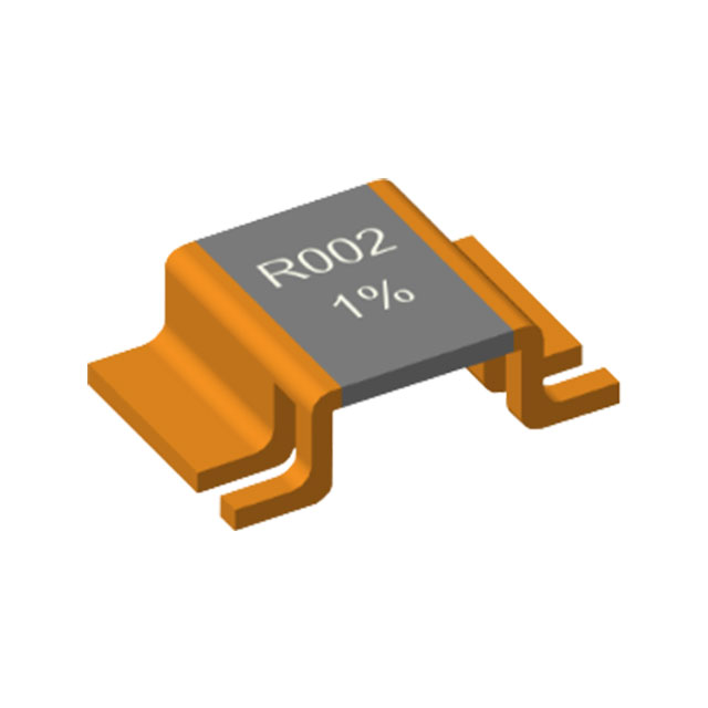
Alloy resistors are integrally formed from highly stable alloy materials such as Manganin, nickel-chromium, and Karma. Featuring milliohm-level ultra-low resistance, extremely low temperature coefficient, high power density, and strong short-time pulse overload capability, they are ideally suited to the high-current, high-precision, and high-reliability working conditions of charging stations. They are widely used in core modules such as precision current sensing, loop overload protection, bleeder loads, and balancing circuits, serving as key passive components that ensure charging accuracy, electrical safety, and equipment service life of charging stations.
2. Working Condition Characteristics of Charging Stations and Core Resistor Selection Requirements
2.1 Typical Working Condition Characteristics
The demanding operating environment of charging station equipment determines the performance thresholds of associated resistors. The core working condition characteristics are as follows: First, continuous high-current operation—DC fast-charging stations can operate at currents exceeding 100 A, while AC stations typically operate at 32 A, with components continuously carrying high currents and generating sustained heat. Second, frequent transient pulse surges—equipment start-stop, battery connection, and voltage switching generate microsecond-level high-power pulse surges, which can easily cause overload damage to ordinary resistors. Third, wide-temperature-range operation—outdoor equipment operates across −40°C to +125°C, with a large temperature span that readily causes resistance drift in ordinary resistors. Fourth, long-term continuous operation—charging stations operate for extended daily hours, imposing extremely high requirements on the aging resistance and fatigue resistance of components.
2.2 Core Resistor Application Requirements
Based on the above working conditions, the requirements of charging stations for core resistors can be summarized in four points: First, high-precision sensing—accurate acquisition of charging current and voltage is the basis for intelligent voltage regulation, overcharge prevention, and overcurrent prevention, requiring high resistance tolerance and minimal temperature drift. Second, high power handling—the ability to continuously and stably carry high currents with excellent heat dissipation, without derating failure at high temperatures. Third, strong pulse withstand capability—the ability to withstand frequent instantaneous power surges, avoiding burnout and resistance shift under pulse conditions. Fourth, high stability—minimal resistance fluctuation across the full temperature range, resistance to aging and humidity, suiting long-term outdoor operation scenarios.
3. Core Technical Advantages of Alloy Resistors (Suited to Charging Station Working Conditions)
Compared with conventional thick-film SMD resistors and carbon-film/metal-film leaded resistors, alloy resistors offer irreplaceable technical advantages under charging station working conditions. Their core performance compatibility is as follows:

3.1 Ultra-Low Resistance and High Precision
Alloy resistors offer a resistance range concentrated between 0.1 mΩ and 10 Ω, with a focus on milliohm-level ultra-low resistance, ideally suited to high-current sensing scenarios in charging stations. Standard models achieve a tolerance of ±1%, while precision automotive-grade models achieve ±0.1%, enabling accurate capture of loop current variations. Combined with the main control chip, this allows precise regulation of charging power, effectively preventing charging abnormalities and battery damage caused by current sensing deviation.
3.2 Extremely Low Temperature Coefficient, Stable Across the Full Temperature Range
Alloy resistors use highly stable alloy substrates, with a temperature coefficient of resistance (TCR) controllable within ±10 to ±50 ppm/°C, far superior to the ±100 to ±300 ppm/°C of ordinary resistors. Across a wide temperature range of −40°C to +125°C, resistance fluctuation is minimal, preventing sampling data distortion caused by outdoor high-temperature exposure or low winter temperatures, and ensuring stable operation of charging stations across all seasons and working conditions.
3.3 High Power Density and Excellent Heat Dissipation
Alloy resistors feature an integrally formed metal structure with excellent thermal conductivity, delivering far higher power density than ordinary resistors in the same package. Taking the 2512 package as an example, a conventional SMD resistor has a rated power of only 0.25 W, whereas an alloy resistor can achieve a continuous rated power of 2 W to 3 W. This enables long-term handling of the continuous high-current loads of charging stations. Combined with large-area PCB copper pouring for heat dissipation, temperature rise is highly controllable, with no risk of overheating failure.
3.4 Superior Short-Time Pulse Withstand Capability
The metal alloy material offers high thermal capacity and excellent thermal stability. For the 10 μs to 100 μs instantaneous high-power pulse surges generated during charging station start-stop and switching, it can withstand short-time overloads of up to one hundred times the rated power, with a wide pulse energy withstand range. This effectively resists instantaneous current surges and eliminates resistor burnout and resistance shift under pulse conditions—a core advantage that ordinary thick-film resistors cannot match for fast-charging station working conditions.
3.5 Low Parasitic Parameters and High Reliability
Alloy resistors feature a leadless, redundant-free structure with minimal parasitic inductance and capacitance, suiting the high-frequency switching circuit conditions of charging stations, reducing signal interference, and ensuring circuit stability. Meanwhile, the integrally formed structure offers high mechanical strength, resistance to vibration, humidity, and aging, adapting to complex outdoor environments with no resistance degradation or solder joint cracking over long-term operation.
4. Segmented Application Scenarios of Alloy Resistors in Charging Stations
Alloy resistors are widely used in core units of AC and DC charging stations, including BMS interface modules, AC/DC conversion modules, DC/DC regulation modules, output protection modules, and load testing modules. The application principles and functions of each scenario are as follows:
4.1 Precision Current Sensing in Charging Loops (Core Application)
The core of charging station control is precisely regulating output current to prevent overcurrent charging from damaging the vehicle battery. Alloy resistors are connected in series in the main charging loop. Based on Ohm's law, I = V/R, a high-precision ADC captures the voltage drop across the resistor, accurately converting it into real-time charging current and feeding the data back to the main control MCU. The main control chip dynamically adjusts output power based on the sensed data, enabling switching between constant-current and constant-voltage charging modes while monitoring current anomalies in real time. This scenario mainly uses 0.5 mΩ to 10 mΩ high-precision, low-TCR SMD alloy resistors, primarily in 2512 and 3921 packages, with a rated power of 2 W to 3 W, meeting the requirements of continuous high-current sensing.
4.2 Overcurrent and Short-Circuit Protection Loops
Short-circuit and overcurrent faults readily occur during vehicle connection, line aging, or load anomalies. Without a fast protection mechanism, equipment and vehicle batteries can easily be damaged. Alloy resistors continuously sense loop current. When the current exceeds a preset threshold, the sensed voltage changes synchronously, prompting the main control chip to immediately trigger relay disconnection and power transistor shutdown, achieving millisecond-level fault protection. This scenario requires resistors with extremely strong instantaneous overload capability, able to withstand the massive pulse current surge at the moment of short circuit without burnout or drift, ensuring circuit safety at the moment of fault.
4.3 Bleeder and Balancing Load Circuits
At the moment a charging station shuts down or loses power, residual high voltage remains in the internal capacitors, posing a safety hazard. As a bleeder load, the alloy resistor quickly dissipates residual charge, enabling rapid voltage decay and ensuring equipment maintenance and personnel safety. In multi-module parallel charging stations, alloy resistors also balance current across power modules, preventing single-module overload and improving overall operational stability. In high-power DC charging station test load banks, nickel-chromium alloy resistors serve as core load elements, withstanding long-term full-power operation to meet equipment aging test requirements.
4.4 Sensing for OBC On-Board Chargers
In the AC/DC and DC/DC conversion circuits of on-board chargers (OBCs) paired with AC slow-charging stations, alloy resistors are used for input and output current sensing, precisely regulating vehicle battery charging current. They suit the stable charging requirements of household slow charging, combining high precision, compact size, and high reliability.
5. Selection Specifications for Charging Station-Specific Alloy Resistors
Based on charging station working conditions and application scenarios, standardized selection rules are established to avoid equipment failures caused by improper selection. Key selection points are as follows:
5.1 Resistance Selection
For main loop high-current sensing: prioritize ultra-low resistance of 0.5 mΩ to 10 mΩ—the lower the resistance, the lower the loop power loss and heat generation, suiting 10 A to 100 A+ high-current conditions. For auxiliary loops and signal sensing: 10 mΩ to 100 mΩ may be used, balancing sensing precision and power consumption. High-resistance resistors must not be used for main loop sensing, to avoid excessive power consumption and severe heating.
5.2 Power Rating Selection (Core Key)
Follow the principle of "long-term derated operation, pulse margin reserved": the actual power corresponding to continuous operating current must be kept within 60% of the resistor's rated power, reserving ample heat dissipation margin. For conventional AC charging stations, select 2 W or higher; for DC fast-charging and ultra-fast charging stations, prioritize 3 W high-power alloy resistors. For outdoor high-temperature conditions and frequent pulse surge scenarios, directly upgrade to higher-power models to eliminate high-temperature derating failure.
5.3 Tolerance and Temperature Drift Selection
For commercial standard charging stations: select conventional alloy resistors with ±1% tolerance and TCR ≤ 50 ppm/°C, meeting general working condition requirements. For high-end ultra-fast and smart charging stations: select precision models with ±0.1% to ±0.5% tolerance and TCR ≤ 15 ppm/°C, eliminating charging precision deviation caused by temperature drift. For extreme cold or high-temperature outdoor scenarios, low-TCR alloy materials must be prioritized to ensure year-round stability.
5.4 Package Selection
For small-to-medium-power AC stations: 2512 package (2 W/3 W), moderate size, high cost-performance, and good heat dissipation. For high-power DC ultra-fast charging stations: 3921 and 4527 large packages, with stronger current-carrying capability and greater pulse withstand margin. For compact smart charging stations: select small-size, high-power SMD models, balancing integration density and performance.
6. Soldering Process and PCB Layout Requirements
The performance of alloy resistors depends on standardized soldering and layout processes. Improper processes can cause resistance shift, excessive temperature rise, and solder joint detachment. Specific requirements are as follows:
Soldering temperature: Reflow soldering peak temperature should be controlled at 230°C to 250°C, with a soldering duration of 30 s to 60 s, avoiding overheating that causes alloy material degradation and resistance drift. Prolonged, repeated high-temperature soldering is prohibited; rework shall not exceed 2 cycles.
PCB layout: Maximize copper pouring on both pads of the resistor, with copper thickness ≥ 1 oz, to increase heat dissipation area and reduce long-term operating temperature rise. Main loop sensing resistors should be laid out in a separate zone, away from high-temperature heat sources such as power transistors and transformers, to avoid thermal stacking. Differential sensing traces should be equal-length and symmetrical to reduce sensing interference and ensure precision.
Reinforcement treatment: For outdoor charging stations with frequent start-stop cycles and high vibration, solder joints may be reinforced with solder mask to prevent cracking caused by thermal cycling and mechanical vibration, improving equipment reliability.
7. Common Failure Modes and Protection Solutions
7.1 Common Failure Phenomena
In practical applications, the main failure modes of alloy resistors include: resistance drift caused by long-term high-temperature aging, localized burnout caused by instantaneous massive pulse surges, overheating failure caused by poor PCB heat dissipation, sensing precision deviation caused by improper soldering processes, and electrode oxidation caused by humid environments.
7.2 Targeted Protection Solutions
Power margin protection: Strictly implement derated design; eliminate long-term full-power or over-power operation; reserve more than 2× power margin for pulse conditions. Heat dissipation optimization: Optimize PCB copper pouring design; auxiliary heat dissipation structures may be used for high-power conditions. Environmental protection: Select automotive-grade, moisture-proof, and corrosion-resistant models, suiting outdoor high/low-temperature and high-humidity environments. Process control: Standardize soldering and rework procedures to eliminate hidden failures caused by poor processes. Regular maintenance: Periodically inspect resistance value and temperature rise of resistors in long-running equipment to identify aging risks in advance.
8. Conclusion
Amid the trend toward higher power, higher precision, and higher reliability in new energy charging stations, ordinary resistors can no longer meet complex working condition requirements. With comprehensive advantages in low temperature drift, high precision, high power density, strong pulse withstand capability, and high stability, alloy resistors have become core components in current sensing, safety protection, and load matching modules of charging stations. Their performance directly determines charging precision, operational stability, and safety of charging stations.
During hardware design and component selection, it is necessary to consider the charging station's power level, operating environment, and current parameters, strictly follow resistance, power, tolerance, and package selection specifications, and combine standardized soldering and PCB heat dissipation processes to fully leverage the performance advantages of alloy resistors—effectively reducing equipment failure rates, extending equipment service life, and providing solid hardware support for the stable, safe, and efficient operation of new energy charging equipment. As ultra-fast charging technology continues to iterate, alloy resistors will continue to advance toward higher power, higher precision, smaller size, and stronger environmental adaptability, meeting the development requirements of high-end fast-charging equipment.

HoVB (4026) Bare Alloy Resistor Series with Outward-Folded Leads
Related Article