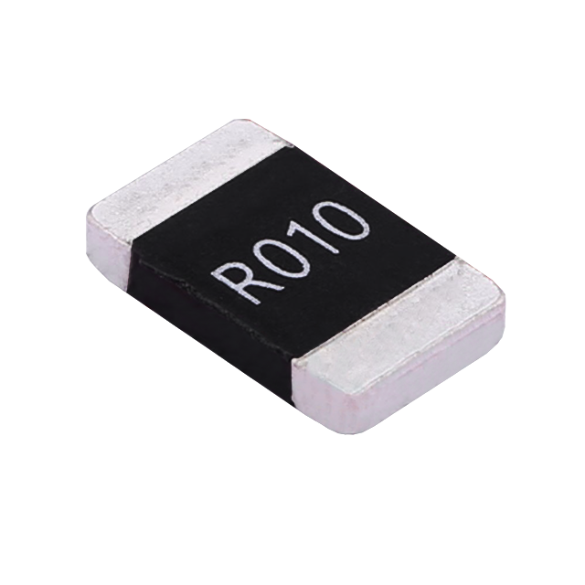
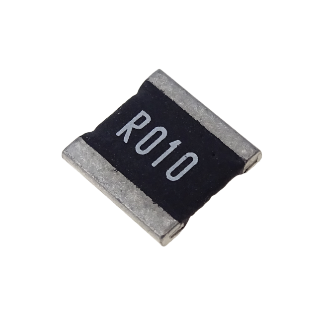
Applications of Alloy Resistors in Power Supply Modules
Traditional thick-film chip resistors and conventional through-hole resistors are prone to issues such as current-sensing inaccuracy, resistance drift, and thermal failure, due to their high TCR, weak pulse-withstanding capability, and poor high-current stability. These limitations make it difficult to meet the design requirements of high-precision, high-reliability power supplies. Alloy resistors, leveraging their key attributes—ultra-low resistance values, low TCR, high power density, strong pulse overload capability, and low parasitic reactance—have become critical components in power modules for current sensing, feedback-loop control, overcurrent protection (OCP), inrush-current suppression, and load-balancing functions.
Keywords: alloy resistors; power modules; current sensing; feedback-loop control; overcurrent protection (OCP); low TCR; pulse withstand capability
I. Introduction
As electronic devices continue to evolve toward higher precision, higher power levels, greater intelligence, and enhanced reliability, power modules are no longer expected to perform basic power-supply functions alone. They are now required to deliver comprehensive functionality, including precise voltage regulation and current stabilization, dynamic load adaptation, active fault protection, and high-efficiency power conversion. Whether deployed in consumer power supplies, industrial control power supplies, high-power server power supplies, or automotive power modules, these systems are routinely subjected to harsh operating conditions such as high-frequency start-stop cycles, abrupt load-step changes, inrush-current surges, and alternating thermal excursions during operation. These demanding environments impose stringent requirements on circuit sensing accuracy, dynamic response speed, and long-term operational reliability.
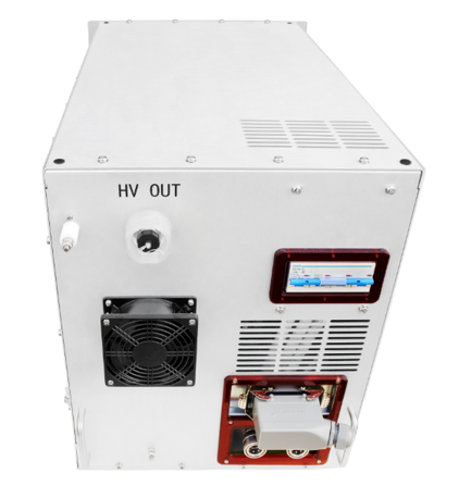
The control core of a power supply module is a closed-loop voltage and current feedback system, in which the stability of the sensing components directly determines the output accuracy and system safety of the power supply. Under high-current, high-frequency, and pulse-surge operating conditions, conventional resistors are prone to issues such as excessive TCR drift, current-sensing errors, thermal stress-induced failure, and high-frequency noise susceptibility. These issues can result in output instability, excessive output ripple, and false triggering of protection circuits. Alloy resistors, manufactured using high-stability alloy materials—including Manganin, Nichrome, and Karma—in an integral molded construction, are ideally suited for the demanding operating environments of power modules and effectively overcome the performance limitations of traditional components. They have become one of the key passive components in modern high-performance power supply modules.
II. Typical Operating Conditions and Critical Component Requirements for Power Modules
① Typical Operating Conditions
The common operating characteristics of various power supply modules can be consolidated into four key aspects, which also represent the critical scenarios that challenge resistor performance.
① -1: high-frequency switching operation — switch-mode power supplies (SMPS) and DC-DC converter modules typically operate at frequencies ranging from 65 kHz to 2 MHz. Under such high-frequency conditions, excessive parasitic inductance and capacitance can lead to signal interference and control-loop oscillation.
① -2:dynamic load-step transients — during equipment start/stop and power-level transitions, load current can change abruptly, generating short-duration, high-energy pulse surges.
① -3: sustained high-current thermal stress — high-power power supply modules can carry operating currents of tens of amperes. Components subjected to continuous high-current operation experience significant thermal accumulation effects.
① -4: wide-temperature-range operation — industrial, automotive, and outdoor power supplies must operate across temperature ranges spanning from −40 °C to +125 °C. Such wide thermal excursions can cause resistance drift in conventional resistors.
② Critical Component Requirements
Based on the aforementioned operating conditions, power modules impose specific technical requirements on current-sensing and protection resistors:
② -1: high precision and low TCR — resistance must remain stable across the entire operating temperature range to ensure accurate current and voltage sensing and to prevent output deviation.
② -2: high power density and low power dissipation — components must be capable of sustaining continuous high-current operation over extended periods with controlled temperature rise and reduced risk of thermal stress-induced failure.
② -3:strong pulse-withstand capability — components must withstand instantaneous power surges resulting from load-step transients and inrush currents during power-up.
② -4:low parasitic inductance — components must be compatible with high-frequency switching conditions, suppress loop interference, and ensure overall power-supply system stability.
② -5:excellent aging resistance and high reliability — components must be suitable for long-term continuous operation, thereby minimizing equipment failure rates.
III. Core Technical Advantages of Alloy Resistors in Power Module Applications
Compared with conventional thick-film chip resistors and metal-film leaded resistors, alloy resistors offer inherent advantages in both material composition and structural configuration, making them ideally suited for the demanding requirements of power modules. Their key application-specific benefits are as follows:
① Ultra-Low Resistance Values for High-Current, Low-Loss Current Sensing
Alloy resistors are available with resistance values spanning from 0.1 mΩ to 10 Ω, with a primary focus on milliohm-level ultra-low resistance, specifically designed for high-current sensing applications. When placed in series with the main power loop, they enable precise current measurement while significantly reducing conduction losses and heat generation, effectively overcoming the high power dissipation and excessive temperature rise associated with conventional high-resistance devices. This contributes to improved overall conversion efficiency of power modules, meeting the energy-saving design requirements of various high-power power supplies.
② Extremely Low TCR for Stable Sensing Across the Full Temperature Range
Alloy resistors achieve a temperature coefficient of resistance (TCR) consistently within ±10 to ±50 ppm/°C—far superior to conventional thick-film chip resistors, which typically exhibit TCR values of ±100 to ±300 ppm/°C. Across the wide temperature range of −40 °C to +125 °C, resistance variation remains minimal, eliminating sensing drift caused by self-heating or ambient temperature fluctuations. This effectively addresses issues such as output instability during cold-start and warm-start transitions and excessive temperature-induced drift, ensuring consistent output accuracy under all operating conditions.
③ High Power Density and Excellent Thermal Stability
Alloy resistors feature a one-piece metal-alloy molded construction that provides exceptional thermal conductivity and high thermal capacity, resulting in power density significantly higher than that of conventional resistors in the same package size. For example, in the common 2512 package, conventional thick-film resistors are rated at only 0.25 W, whereas alloy resistors can achieve continuous rated power of 2 W to 3 W—representing a multiplefold increase in power density. Under sustained high-current operation, temperature rise is gradual and thermal equilibrium is highly stable, with no thermal runaway or progressive resistance drift, making them well-suited for long-term continuous operation of power modules.
④ Superior Pulse Withstand Capability for Surge Current Suppression
During power-up, load short circuits, or abrupt power transients, microsecond-to-millisecond surge pulses are generated—these are the primary causes of resistor failure. Alloy resistors, with their high thermal capacity metallic substrate and robust structural integrity, can withstand pulse surges of up to hundreds of times their rated power for short durations. Under narrow-pulse conditions from 10 μs to 10 ms, they exhibit no burnout or resistance shift, effectively withstanding various instantaneous surges in power supply applications and significantly enhancing the system's immunity to interference and fault tolerance.
⑤ Low Parasitic Inductance for High-Frequency Switching Applications
Alloy resistors feature a minimized lead structure, resulting in extremely low parasitic inductance and capacitance, and excellent high-frequency performance. In MHz-level high-frequency switching power supplies, they effectively mitigate signal oscillation, phase shift, and increased ripple caused by parasitic effects. This optimizes closed-loop control stability, reduces high-frequency noise, and ensures clean output waveforms and stable power supply operation.
IV.Detailed Application Scenarios of Alloy Resistors in Power Modules
Alloy resistors are utilized across the entire power module functional chain—covering input, power conversion, output, and protection stages. In equipment such as switch-mode power supplies (SMPS), DC-DC regulator modules, industrial high-power supplies, server power supplies, and fast-charging adapters, their primary application scenarios can be classified into five main categories. The specific functions and recommended specifications for each are detailed below:
① Precision Current Sensing in Output Circuits (Primary Application)
Current sensing is fundamental to voltage regulation and constant-current control in power supplies. Alloy resistors are placed in series with the main output loop of the power supply, converting the real-time current into an accurate voltage signal based on Ohm's law, which is then transmitted to the main controller IC and the ADC sampling unit. The controller dynamically adjusts the PWM duty cycle based on the feedback signal to achieve constant-voltage and constant-current output, adapting to dynamic load variations and preventing output voltage and current fluctuations. This represents the primary application of alloy resistors in power modules. Typical selection parameters include resistance values ranging from 1 mΩ to 20 mΩ, tolerance of ±1%, and low TCR. For high-power supplies, large-package high-power types such as 2512 and 3921 are preferred to ensure accurate, distortion-free high-current sensing.
② Closed-Loop Feedback Network Calibration
High-precision industrial power supplies and instrumentation power supplies demand extremely low output ripple and high line and load regulation, relying on alloy resistors to construct precise feedback networks. Compared with conventional resistors, alloy resistors are free from TCR-induced drift and high-frequency noise interference, consistently providing stable and accurate reference signals for the control loop. They suppress low-frequency jitter and high-frequency oscillation, improving output linearity and load regulation, and ensuring smooth output transitions during light-load, heavy-load, and full-load switching without voltage step changes.
③ Inrush Current Limiting and Soft-Start Assistance
During cold start-up, the input capacitors generate substantial inrush currents that can easily damage power MOSFETs and rectifier components. Alloy resistors serve as current-sensing and current-limiting elements, suppressing peak inrush current during power-up. Working in conjunction with soft-start circuits, they enable gradual current rise, preventing instantaneous surge damage to circuit components and enhancing start-up stability and device service life. They are critical protection components at the input stage of power supplies.
④ Overcurrent and Short-Circuit Fault Protection
When the output-side load experiences short circuits, overloads, or abnormal leakage, the loop current can spike instantaneously. Alloy resistors continuously monitor the loop current; once the current exceeds the preset threshold, they immediately feed back an abnormal signal, allowing the main controller to rapidly turn off the power switching devices and shut down the output. This achieves millisecond-level fault protection, preventing power supply burnout and downstream equipment damage. This application requires resistors with exceptionally strong instantaneous overload capability to withstand extreme short-circuit pulse surges without failure.
⑤ Multi-Module Load Balancing and Residual Voltage Discharge
High-power power supplies commonly employ a multi-module parallel operating configuration. Alloy resistors enable current balancing among parallel modules, preventing individual module overload and overheating, thereby improving overall system power utilization and operational stability. Additionally, during power-off or standby, alloy resistors can rapidly discharge residual voltage in the circuit, eliminating potential safety hazards and enhancing equipment maintenance and operational safety.
V. Selection Guidelines for Alloy Resistors in Power Module Applications
Based on the typical operating characteristics of power modules—including high-frequency switching, high-current operation, pulse surges, and wide-temperature-range performance—standardized selection criteria are established to prevent issues such as insufficient accuracy, thermal stress-induced failure, and protection-circuit malfunctions caused by improper component selection.
① Resistance Value Selection
For high-current sensing in main power loops: resistance values in the range of 1 mΩ to 20 mΩ are recommended, balancing sensing accuracy with low power dissipation. Lower resistance values result in reduced conduction losses and temperature rise, making them suitable for applications with operating currents above 10 A. For auxiliary circuits with small to medium currents: resistance values from 20 mΩ to 100 mΩ may be selected to balance sensing sensitivity and power dissipation. High-value resistors must not be used for main-loop current sensing, as this would lead to excessive long-term power dissipation and thermal accumulation-induced failure.
② Power Rating Selection (Critical Criteria)
The derating design principle shall be strictly observed: under normal operating conditions, the actual power dissipation of the resistor should be maintained within 60 % of the rated power. Under high-frequency ripple, frequent load-step transients, and elevated temperature conditions, derating to 50 % of rated power is recommended to provide sufficient margin for pulse surges and thermal dissipation. For general adapter power supplies, 2 W devices are typically adequate; for industrial high-power supplies and server power supplies, alloy resistors with power ratings of 3 W or higher are preferred. Operation at or above the rated power limit must be strictly avoided.
③ Precision and TCR Selection
For general commercial power supplies: resistors with tolerance of ±1 % and TCR ≤ 50 ppm/°C are suitable for standard voltage regulation requirements. For high-precision instrumentation power supplies, industrial power supplies, and medical power supplies: precision-grade resistors with tolerance of ±0.1 % to ±0.5 % and TCR ≤ 15 ppm/°C are required to eliminate output deviations caused by temperature-induced drift. For power supplies operating in high-temperature or poorly ventilated enclosed environments, low-TCR, high-temperature-rated alloy resistors must be selected.
④ Package Selection
For compact adapters and low-power modules: 1206 and 2512 packages are recommended for their small footprint and cost-effectiveness. For medium- to high-power industrial power supplies: larger packages such as 3921 and 4527 are preferred, offering enhanced current-carrying capacity and greater pulse-withstand margin. For compact high-density power supplies: small-footprint, high-power surface-mount alloy resistors should be selected to balance integration density with reliability.
VI. PCB Layout and Soldering Process Requirements
The performance of alloy resistors depends on proper hardware implementation. Improper PCB layout and soldering practices can lead to latent defects such as resistance drift, excessive temperature rise, sampling noise, and solder-joint failure.
PCB Layout Guidelines:
-
Resistor pads shall be designed with maximum copper coverage. Copper thickness should be ≥ 1 oz (35 µm) to enhance heat spreading and reduce steady-state temperature rise.
-
Current-sensing resistors should be placed in a dedicated area, isolated from heat sources such as transformers, power MOSFETs, and diodes, to prevent thermal coupling and measurement errors.
-
Differential sensing traces must be routed with equal length, symmetry, and minimal distance to minimize high-frequency noise pick-up and ensure sensing accuracy.
-
High-current loops must be routed separately and should not be intermingled with low-level signal traces to avoid ground bounce and crosstalk.
Soldering Process Requirements:
-
Reflow soldering peak temperature should be controlled between 230 °C and 250 °C, with a dwell time of 30 to 60 seconds, to prevent alloy material degradation and resistance drift caused by excessive heat exposure.
-
Rework soldering shall be limited to no more than two times, and prolonged high-temperature baking of solder joints is prohibited.
-
After soldering, the board surface must be kept clean to prevent flux residue from corroding the terminations, which could compromise long-term reliability.
VII. Common Failure Modes and Countermeasures
① Typical Failure Phenomena and Root Causes
Common failure modes of alloy resistors in power modules include:
-
Resistance drift induced by prolonged high-temperature operation, resulting in degradation of output accuracy.
-
Localized burnout or open-circuit failure caused by inrush current surges or short-circuit pulse stresses.
-
Thermal accumulation due to inadequate PCB heat dissipation, accelerating device aging.
-
Current-sensing signal distortion due to layout-induced noise, triggering false protection activation.
-
Electrode oxidation and increased contact resistance resulting from exposure to humid or corrosive environments.
② Targeted Countermeasures
-
Power derating protection: The derating design principle must be strictly followed. For pulsed-load applications, a power margin of at least twice the rated power should be reserved to withstand instantaneous surge events.
-
Thermal management protection: PCB copper pour for heat spreading must be optimized. For enclosed or high-temperature power supplies, auxiliary heat-dissipation structures such as heat sinks or thermal vias may be added.
-
Environmental protection: For industrial and outdoor power supplies, automotive-grade (AEC-Q200) alloy resistors with moisture resistance and high-temperature tolerance should be selected.
-
Process control protection: Standardized soldering and PCB layout procedures shall be implemented to eliminate latent defects caused by improper routing or soldering.
-
Preventive maintenance protection: Regular inspection of resistor temperature rise and resistance drift shall be performed to identify aging-related degradation early, ensuring long-term stable operation of the power supply.
VIII. Conclusion
As power modules continue to evolve toward higher switching frequencies, greater precision, improved efficiency, and enhanced reliability, conventional resistors are no longer adequate for complex dynamic operating conditions. Alloy resistors, with their combined performance benefits—including low power dissipation, low TCR, high precision, superior pulse-withstand capability, and excellent long-term stability—have effectively resolved critical pain points such as current-sensing distortion, output instability, poor surge immunity, and susceptibility to thermal stress-induced failure. They have become indispensable components in closed-loop control and protection systems of power supplies, directly determining output accuracy, operational stability, and service life.
During the hardware design and component selection process for power supplies, selection guidelines for resistance value, power rating, tolerance, and package type must be strictly followed, taking into account power level, operating frequency, load characteristics, and environmental conditions. These should be complemented by standardized PCB layout and soldering processes to fully leverage the performance advantages of alloy resistors. As high-power, high-density power supply technologies continue to advance, alloy resistors are expected to evolve toward higher power ratings, improved precision, smaller footprints, and greater environmental adaptability—consistently enabling technological innovation and quality enhancement across a wide range of power supply equipment, including industrial power supplies, renewable-energy power supplies, server power supplies, and precision instrumentation power supplies.
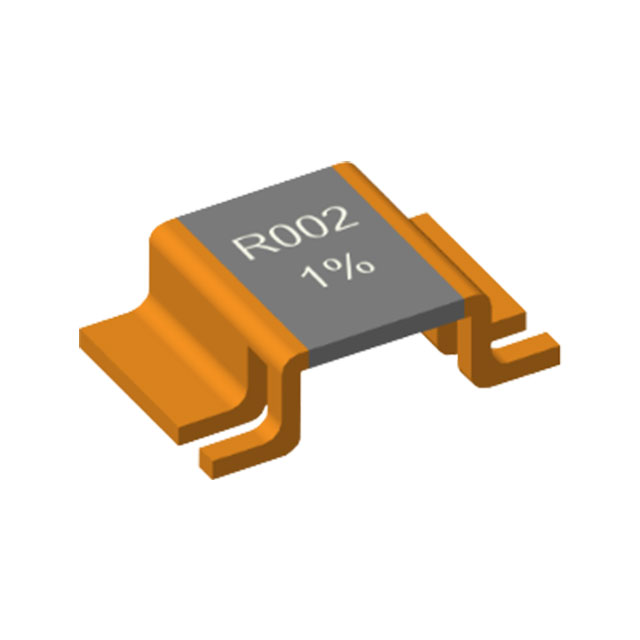
HoVB (4026) Bare Alloy Resistor Series with Outward-Folded Leads
Overview of Non-Inductive Resistor Technology
Related Article