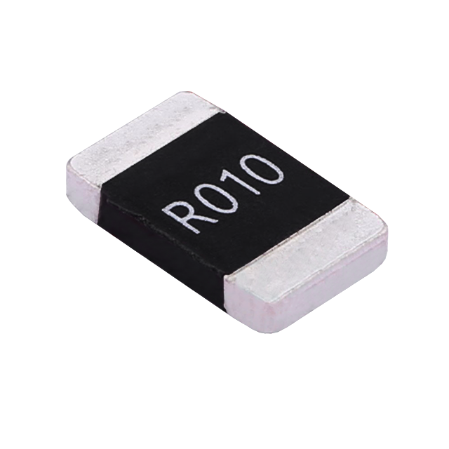
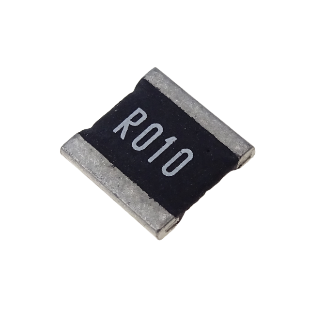
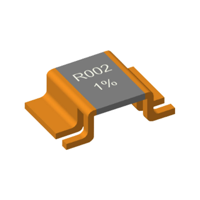
Overview of Non-Inductive Resistor Technology
I. Core Definition and Working Principle of Non-Inductive Resistors
Conventional resistors, such as traditional wirewound types, inherently form closed magnetic loops when current flows through them due to their structural characteristics, resulting in a certain degree of parasitic inductance. As the circuit operating frequency increases (typically beyond 100 kHz), the inductive reactance (XL = 2πfL) rises significantly and superimposes on the resistor's intrinsic impedance, causing the actual performance to deviate from the designed values and potentially leading to circuit resonance or interference with signal transmission.
The core design philosophy of non-inductive resistors is to neutralize or attenuate the magnetic field generated by the current through structural optimization, thereby minimizing parasitic inductance—typically below 1 nH, with high-end metal foil non-inductive resistors achieving values as low as 0.01 nH. This ensures that under high-frequency and pulsed operating conditions, the impedance is predominantly determined by the resistance value, maintaining stable performance. Three common structural optimization approaches are employed: the first is the bifilar winding method, in which two parallel wires are wound in the same direction on an insulating bobbin with currents flowing in opposite directions, causing the generated magnetic fields to cancel each other out; the second is the non-wirewound structure, which involves depositing resistive materials (such as metals or carbon) onto a ceramic substrate and laser-trimming them to shorten the current path and reduce loop area; the third is planarization design, which utilizes multilayer printed or planar spiral structures to create symmetrically distributed current paths, avoiding the formation of three-dimensional coils that would otherwise produce inductive effects.
II. Main Classifications and Characteristics of Non-Inductive Resistors
Based on differences in structure, materials, and application scenarios, non-inductive resistors are primarily categorized into the following five types. Each type offers distinct strengths in terms of performance, size, power handling, and other aspects, catering to a variety of application requirements:
(1) Non-Inductive Wirewound Resistors
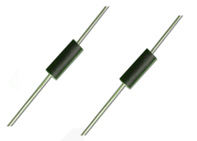
These resistors employ bifilar or multifilar winding techniques, using alloy resistance wires such as Constantan or Manganin wound onto insulating cores made of ceramic, quartz, or similar materials, with surfaces typically coated with high-temperature-resistant finishes. Their key characteristics include high power-handling capacity (ranging from a few watts to several kilowatts), a wide resistance range (0.1 Ω to 1 MΩ), and excellent thermal stability. They are well-suited for high-frequency, high-power applications such as braking circuits in industrial variable-frequency drives and loads for high-voltage equipment. However, they are relatively large in size and offer slightly lower precision compared to thin-film non-inductive resistors.
(2) Thick-Film Non-Inductive Resistors
These resistors are fabricated using ceramic substrates, onto which metal pastes (such as ruthenium-based pastes) are applied via screen printing. The resistive layer is then formed through high-temperature sintering, with resistance values subsequently trimmed by laser etching. Key characteristics include compact size, high precision (resistance tolerance as low as ±0.1%), extremely low parasitic inductance, and excellent frequency response. They are well-suited for high-frequency, high-precision, and miniaturized applications such as RF circuits and precision instrumentation. However, their power-handling capacity is relatively limited, typically not exceeding 50 W, and when failure occurs, they tend to fail in an open-circuit mode, which offers a higher degree of safety.
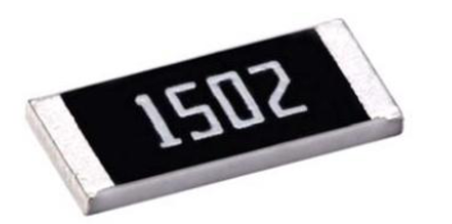
(3) Thin-Film Non-Inductive Resistors
These resistors are manufactured using vacuum evaporation, sputtering, and other thin-film deposition techniques to deposit metal or alloy films—such as nickel-chromium and gold-palladium—onto insulating substrates, with precise resistor patterns subsequently defined through photolithography. Their core advantages include extremely high precision (tolerance as low as ±0.01%), a low temperature coefficient of resistance (TCR, typically below ±10 ppm/°C), and ultra-low parasitic inductance and distributed capacitance. They are ideally suited for ultra-high-frequency and ultra-high-precision applications, including aerospace equipment and high-end medical instruments. However, they entail relatively high production costs and offer limited power density.
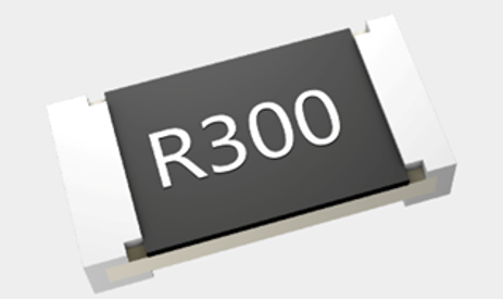
(4) Metal Foil Non-Inductive Resistors
These resistors are manufactured by pressing metal alloys into thin foils, onto which precision resistor patterns are defined via photolithography, followed by encapsulation. They achieve parasitic inductance as low as 0.0005 μH, exhibit ultra-low noise, and offer exceptional stability, with a temperature coefficient of resistance (TCR) as low as ±5 ppm/°C. Representing the highest-performing category of non-inductive resistors currently available, they are primarily employed in ultra-high-frequency, ultra-high-precision applications such as precision measurement equipment and calibration instruments. However, they are costly and have limited power-handling capacity.
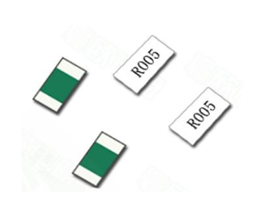
(5) High-Power Non-Inductive Load Resistors
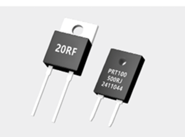
These resistors are purpose-built for high-power applications, featuring ceramic or metal housings with internally optimized non-inductive structures. Certain models are equipped with heat sinks and can achieve power ratings of 3000 W or higher. They are primarily deployed in power equipment, pulse power supplies, motor braking systems, and other similar scenarios, where their core function is to absorb surplus electrical energy and buffer current surges, thereby ensuring stable circuit operation. These resistors typically exhibit relatively low resistance values—ranging from a few milliohms to several tens of ohms—along with high current-carrying capacity.
III. Key Technical Specifications of Non-Inductive Resistors
When selecting and applying non-inductive resistors, special attention must be paid to the following core specifications to ensure compatibility with circuit design requirements and to prevent device damage or circuit malfunction due to parameter mismatches:
(1) Nominal Resistance and Tolerance
Nominal resistance is the fundamental specification of a non-inductive resistor, expressed in ohms (Ω), with common values spanning from milliohm (mΩ) to megohm (MΩ) ranges. Selection should be based on precise circuit current-limiting and voltage-divider requirements. Tolerance indicates the allowable deviation between actual resistance and the nominal value, with standard grades including ±5 %, ±1 %, ±0.1 %, and ±0.01 %. High-frequency and precision circuits require high-precision components (tolerance of ±1 % or better), whereas general industrial applications may use ±5 % tolerance devices to reduce costs.
(2) Rated Power and Peak Power Capability
Rated power is defined as the maximum power dissipation a non-inductive resistor can sustain during continuous long-term operation under specified ambient temperature conditions (typically 25 °C), expressed in watts (W). Exceeding the rated power may result in overheating, resistance drift, or catastrophic failure. In practice, a design margin of at least 30 % above the actual circuit power dissipation should be reserved. For pulsed-duty applications, special consideration must be given to peak power capability to ensure the device can withstand short-duration, high-energy surges. For instance, braking resistors in variable-frequency drives require peak power ratings substantially higher than their continuous power ratings.
(3) Parasitic Inductance and Frequency Response
Parasitic inductance is the defining parameter that differentiates non-inductive resistors from conventional resistors. In most applications, it is specified to be below 1 nH; for high-frequency applications such as those in the gigahertz range, products with parasitic inductance below 0.1 nH are required. Frequency response characterizes the impedance stability of the resistor across different operating frequencies. Premium non-inductive resistors exhibit smooth impedance curves with no abrupt transitions across their specified frequency range—typically from 1 kHz to 17 GHz—within which inductive reactance effects are negligible, thereby ensuring stable circuit performance.
(4) Temperature Coefficient of Resistance (TCR)
TCR quantifies the relative change in resistance per 1 °C change in ambient temperature, expressed in parts per million per degree Celsius (ppm/°C). Lower TCR values indicate superior temperature stability. For general-purpose applications, devices with TCR below ±50 ppm/°C are typically adequate; for precision and high-temperature environments, products with TCR below ±10 ppm/°C are recommended to prevent temperature-induced resistance drift that could compromise circuit accuracy.
(5) Other Critical Specifications
Additional specifications include operating temperature range (typically −55 °C to +155 °C, with some high-temperature variants rated up to +200 °C or above), insulation resistance (≥10 GΩ to ensure safety isolation), package dimensions—surface-mount device (SMD) packages such as 0805 and 2512, and through-hole packages such as TO-220, which must be compatible with PCB layout—as well as compliance certifications including RoHS environmental certification and AEC-Q200 automotive-grade qualification for automotive electronics applications.
IV. Application Scenarios for Non-Inductive Resistors
Leveraging their core advantages of low parasitic inductance and high stability, non-inductive resistors are predominantly deployed in inductance-sensitive, high-precision, or high-power applications across a broad spectrum of industries, including electronics, power systems, medical devices, and aerospace. Key application scenarios are detailed below:
(1) High-Frequency Electronic Equipment
Applications include radio-frequency (RF) circuits, high-frequency test and measurement equipment (such as oscilloscope probes and signal generator loads), high-speed digital circuits (termination resistors), and microwave communication systems. In these settings, non-inductive resistors are used for impedance matching, signal attenuation, and current limiting, preventing inductive effects from degrading signal integrity and ensuring high-fidelity signal transmission.
(2) Power Electronics Equipment
This category constitutes the primary application domain for non-inductive resistors, encompassing variable-frequency drives, inverters (including photovoltaic and wind-turbine inverters), uninterruptible power supplies (UPS), DC-link braking circuits, and thyristor snubber circuits. Their functions include surge-current absorption, regenerative braking energy dissipation, voltage-spike suppression, and power-semiconductor protection, all of which contribute to stable and reliable equipment operation.
(3) Precision Instrumentation
These applications include precision bridges, calibration standards, ammeters, voltmeters, and similar devices, where non-inductive resistors are employed for current sensing and voltage-divider networks. Leveraging their high accuracy, low TCR, and low-noise characteristics, they ensure measurement integrity. Certain high-end instruments further utilize metal-foil non-inductive resistors to achieve the highest possible measurement precision.
(4) Medical and Aerospace Equipment
Medical devices such as MRI systems and high-frequency therapy generators, along with aerospace systems including telemetry instruments and satellite avionics, demand exceptional resistor stability and reliability. Non-inductive resistors maintain consistent performance under high-frequency and extreme-temperature conditions, mitigating failure risks. Some military-grade and aerospace applications require high-frequency non-inductive resistors rated up to 17 GHz to satisfy stringent performance criteria.
(5) Other Application Areas
Additional applications include audio power amplifiers (output-stage protection resistors), automotive electronics (battery management systems in new-energy vehicles), electric traction systems for mass transit (metro and light-rail vehicles), and high-voltage installations such as switchgear and transformer neutral-grounding networks. In these scenarios, non-inductive resistors perform current-limiting, loading, and overvoltage-protection functions, ensuring safe and dependable system operation.
V. Selection Criteria and Application Precautions for Non-Inductive Resistors
(1) Selection Criteria
①: Prioritize core application requirements: Based on operating frequency, power level, and precision needs, select the appropriate resistor type. For instance, thin-film and metal-foil types are preferred for high-frequency, high-precision applications, whereas non-inductive wirewound and high-power load types are better suited for high-power applications.
②: Verify key specifications: Ensure that nominal resistance, rated power (with adequate derating margin), parasitic inductance, and TCR comply with design requirements to avoid device failure due to under-specification.
③: Evaluate mounting and thermal management: SMD types are ideal for miniaturized, automated assembly processes, while through-hole types are more appropriate for manual soldering and high-power heat-dissipation scenarios. High-power non-inductive resistors must be used with appropriately sized heat sinks to ensure effective heat removal.
④: Balance cost and reliability: For critical high-end applications, prioritize high-precision, high-stability components; for general-purpose use, cost-effective alternatives such as thick-film or non-inductive wirewound types may be considered. Additionally, verify product certifications to ensure compliance with relevant industry standards (e.g., RoHS, AEC-Q200).
(2) Application Precautions
① : Avoid over-power and over-voltage operation: Strictly adhere to rated operating conditions. Over-power operation may cause overheating and resistance drift; over-voltage conditions may lead to insulation breakdown or dielectric failure.
② : Implement proper thermal management: High-power non-inductive resistors generate substantial heat during operation. PCB layout should allocate adequate clearance and airflow, and heat sinks should be employed where necessary to prevent performance degradation and premature aging due to excessive junction temperatures.
③ : Mitigate parasitic effects at high frequencies: Confirm the resistor's specified frequency-response range during selection. Operation beyond the rated frequency limits may cause parasitic inductance effects to become significant, compromising circuit performance.
④ : Observe proper soldering practices: For SMD non-inductive resistors, avoid prolonged high-temperature soldering to prevent solder wicking into the resistor body, which could damage the resistive element. For through-hole devices, ensure proper pin wetting and avoid cold-solder joints.
⑤ : Perform periodic inspection and maintenance: In equipment subject to continuous high-load operation, periodically verify resistance values and operating temperatures, and proactively replace aged or degraded components to maintain long-term circuit stability and reliability.
VI. Conclusion
As critical components in high-frequency, precision, and high-power circuits, non-inductive resistors overcome the inherent inductive limitations of conventional resistors through specialized structural designs. Their advantages—low parasitic inductance, high stability, and high precision—render them indispensable across electronics, power systems, medical devices, aerospace, and numerous other sectors. With ongoing technological advancement, non-inductive resistors are trending toward higher operating frequencies, miniaturization, increased power density, and enhanced precision. Domestic manufacturers continue to close the technology gap with international peers through independent research and development.
When selecting and applying non-inductive resistors, engineers must comprehensively evaluate circuit requirements with particular emphasis on nominal resistance, rated power, parasitic inductance, and TCR, while simultaneously considering mounting, thermal, and cost factors. Only through such a holistic approach can the full performance potential of these components be realized, ensuring stable and reliable equipment operation.
Applications of Alloy Resistors in Power Supply Modules
Core Discrepancies Between Exposed Alloy Resistors and Encapsulated Alloy Resistors
Related Article