Alloy resistor heat dissipation design: a hierarchical strategy from source to system
author: Milliohm Electronic
2025-10-23

The heat dissipation design of alloy resistors must be considered based on factors such as the product's power level, space limitations, and operating environment (such as temperature and vibration). The core goal is to control the resistor temperature within the rated range (typically -55°C to 125°C, with high-power models reaching 150°C) to avoid resistance drift, reliability degradation, or even burnout due to overheating. The following are general heat dissipation design principles and specific measures:
I: Source Control: Reduce Heat Dissipation Pressure by Selecting Based on Power and Parameters
The premise of heat dissipation design is to reduce heat generation. Optimizing heat dissipation requirements at the source is crucial.
① Power Derating Design: Allow for a Safety Margin
The power loss formula for alloy resistors is P = I^2R (I is the operating current, R is the resistance value). In actual applications, power derating must be strictly adhered to—that is, the actual power loss must be significantly lower than the rated power.
General Principle: Design according to the derating power curve provided in the alloy resistor data sheet. Derating by 2-3 times (the higher the ambient temperature, the greater the derating factor). If the ambient temperature exceeds 50°C, it is recommended to derate by more than 2 times (e.g., if the actual power is 3W, choose 10W or higher). Reason: The rated power of resistors is usually based on testing at an ambient temperature of 25°C. The rated power will decrease in high-temperature environments (e.g., at 125°C, the rated power may be only 50% of that at 25°C).
② Large-size packages are preferred: The package directly determines heat dissipation capacity, so the appropriate size and structure should be selected based on power requirements:
Milliohm Electronics' product line offers chip alloy resistors in common packages such as 0805, 1206, 2512, 3825, and 4527 (for medium and high power). Plug-in resistors include TO-220, TO-263, TO-247, HoVB, HoBH, and "X" shapes. Depending on the product, larger size increases the heat dissipation area and lowers the thermal resistance.
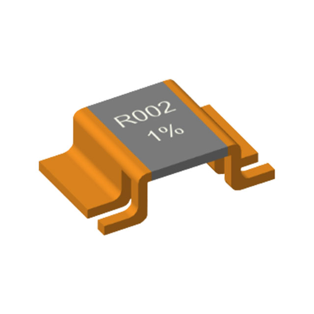
For chip resistors: Choose products with exposed alloy (such as the Ho-LRS series, Ho-LRS(JZ) series, and Ho-VB series). The bottom metal pad directly contacts the PCB copper foil, reducing thermal resistance by 30%-50% and accelerating heat transfer to the PCB.
Plug-in type: Bare plug-in alloy resistors (such as Ho-LR-JZ, Ho-CY, and solder resistor series) and packages with metal casings or heat sinks (such as TO-220, TO-247, and molded chip packages). The casing can directly dissipate heat or be connected to an external heat sink, suitable for high-power scenarios above 10W.
II. PCB Design: Creating an Efficient Thermal Conductivity Path
Heat from alloy resistors is primarily conducted and diffused through the PCB copper foil and solder pads. Therefore, PCB design is a key component in heat dissipation (especially for SMD resistors).
① Enhance the thermal conductivity of the copper foil and solder pads
①-1: Thickened Copper Foil: Use a PCB with a copper thickness of 2oz (70μm) or thicker (3oz-4oz is common for power products). Copper's thermal conductivity (401W/(m・K)) is much higher than that of FR4 substrate, reducing the thermal resistance of the current path and accelerating heat dissipation.
①-2: Enlarge the solder pad and heatsink:
The solder pad size should match the resistor package, and a heatsink covering 3-5 times the area of the solder pad should extend outward (for example, the solder pad of a 2512 resistor is approximately 2.5mm × 1.2mm, and the heatsink covering can be expanded to 5mm × 3mm). This creates a "heat diffusion zone" to disperse heat across a larger copper foil area. The heatsink copper foil must be connected to the PCB's ground plane (GND) or power plane (vias), utilizing the entire copper layer as a heat sink.
② Optimize Thermal Via Design
Densely arrange thermal vias on the resistor pads or thermal foil to conduct heat from the top copper foil to the bottom or inner layers of the PCB. Via parameters: 0.3-0.5mm diameter, 1-2mm spacing, with the number of vias determined by the power rating (e.g., 4-6 vias for a 2W resistor, 8-12 for 5W and above). Via Treatment: Vias must be fully copper-filled (avoiding hollow vias that result in poor thermal conductivity) and connected to a large copper surface on the bottom or inner layers (such as the ground plane), utilizing the copper layers of the multilayer PCB to maximize heat dissipation.
③ Avoid Heat Concentration in Layout
Alloy resistors should be kept away from other high-heat-generating components (such as power transistors, inductors, and transformers), with a spacing of at least 5-10mm (≥15mm for high-power applications) to prevent localized high temperatures caused by thermal radiation. Multiple alloy resistors (such as current sensing resistors in multi-phase power supplies) should be arranged in a dispersed layout, with adequate heat dissipation gaps (especially in air-cooled scenarios) to avoid concentrated heat.
III. Auxiliary Heat Dissipation Structures: Enhanced Heat Dissipation (Medium-to-High Power Scenarios)
When alloy resistors have high power losses, PCB heat dissipation alone may be insufficient. Therefore, auxiliary structures are necessary to accelerate heat transfer to the outside world.
① Heat Sink and Thermal Interface Materials
①-1 Chip Resistors: Attach a high-thermal-conductivity silicone pad (thermal conductivity 2-5 W/(m・K)) to the resistor surface. Connect the other end to a metal heat sink (aluminum alloy or copper). The heat sink can be fixed to the product housing or chassis, creating a thermal path from resistor to silicone pad to heat sink to the housing. Note: The silicone pad should be compressed by 0.1-0.3 mm to ensure a tight fit with the resistor surface (avoid air gaps, as air has a thermal conductivity of only 0.026 W/(m・K) and will significantly hinder heat dissipation).
①-2 Insert Resistors: Alloy resistors in a TO-220 package can be directly secured to a heat sink by screwing the metal housing. Apply thermal grease (thermal conductivity 3-8 W/(m・K)) to the contact surface to reduce contact thermal resistance.
② Heat Dissipation in Potting and Sealed Environments
In sealed or dusty/humid environments (such as outdoor equipment and automotive electronics), a thermally conductive potting compound (such as epoxy resin, with a thermal conductivity of 0.8-2 W/(m・K)) can be used to pot the alloy resistor with surrounding components. Heat is transferred to the housing through the potting compound, making it suitable for applications where a heat sink cannot be installed.
③ Forced Cooling (High-Power Applications): When resistor losses are excessive, active cooling may be required.
③-1 Air Cooling: Place a fan near the resistor to ensure direct airflow over the resistor surface, dissipating heat through convection. (Suitable for 10-50W applications, such as industrial power supplies.)
③-2 Liquid Cooling: A water-cooling plate (such as an automotive motor controller) is attached below the resistor or to the heat sink. Coolant (water or antifreeze) circulates through pipes to remove heat. This method is suitable for high-power applications.
IV. Summary
The heat dissipation design of alloy resistors should follow a hierarchical strategy: "derating selection → PCB conduction → auxiliary heat dissipation." The core is to control the temperature within a safe range by "reducing heat generation (selection), accelerating heat transfer (PCB and structure), and enhancing heat dissipation (cooling)." In actual applications, it is necessary to consider product power, space constraints (such as the compact design required for consumer electronics), and environmental requirements (such as the ultra-low temperature drift and vibration resistance required for automotive standards) to flexibly select a solution to ensure the long-term stable operation of the resistor.
Layout design for parallel use of Kelvin structure resistors
Application advantages and selection recommendations of alloy resistors in on-board chargers (OBC)
Related Article
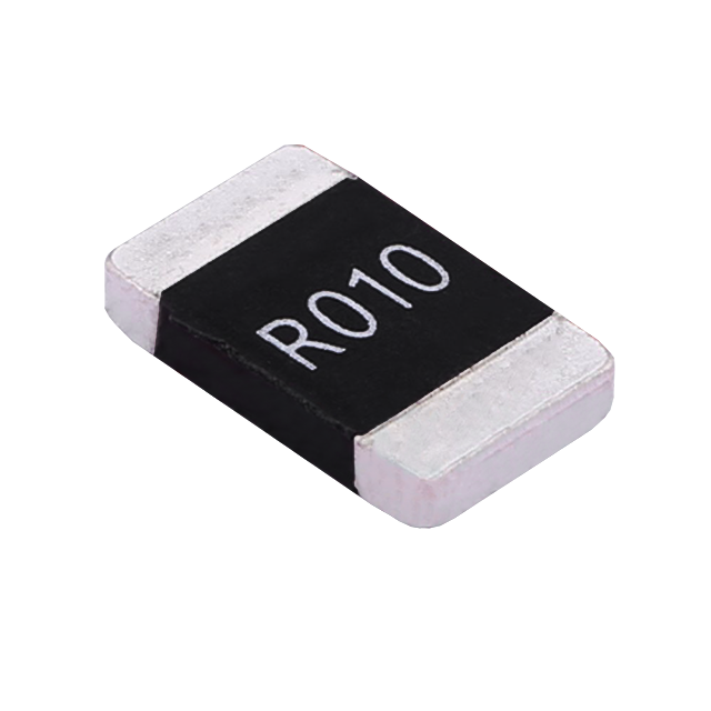
Key performance features: high power handling, ultra-low temperature drift, high overload withstand capability, low inductance at high frequency, and automotive-grade high reliability.
HoCG4527 Automotive Grade Molded Alloy Resistor
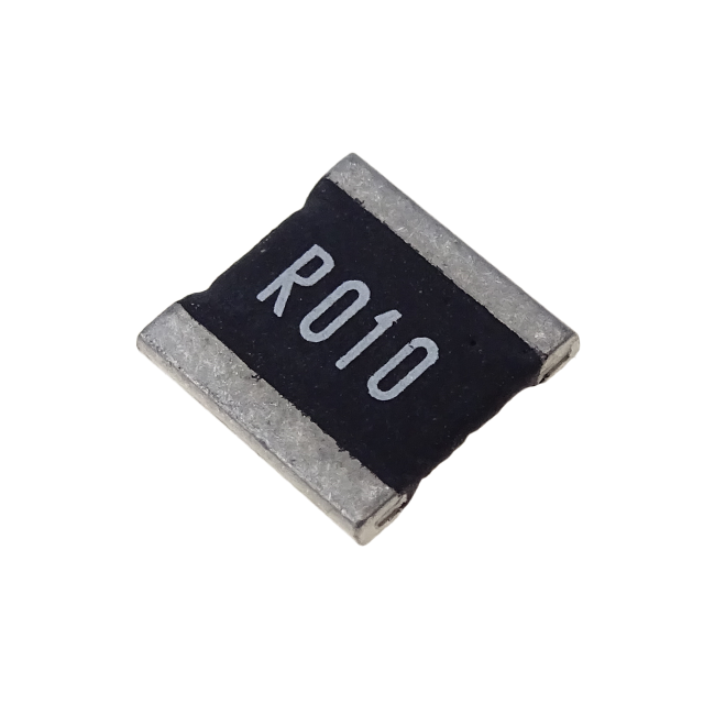
Key features: ultra-high current-carrying capability, ultra-high stability, ultra-low temperature drift, and low inductance at high frequency.
HoCG2728 Automotive Grade Molded Alloy Resistor

Alloy resistors, with their unique technical advantages—ultra-low resistance, low temperature drift, high power handling, low parasitic parameters, and strong pulse withstand capability—have become core components in current sensing, overload protection, and load matching circuits for EV charging stations.
Alloy Resistor Applications in New Energy