The impact of parasitic inductance on circuits in resistor applications
author: Milliohm Electronic
2025-09-12
I: Sources of Parasitic Inductance
Parasitic inductance is not a "natural property" of resistors, but rather arises from their physical structure and current characteristics. When current flows through a resistor, the law of electromagnetic induction generates a magnetic field around the conductor. The resistor's leads, internal conductive paths, and even the traces connecting the resistor on the PCB act like tiny "coils." When the current changes, the magnetic flux within these "coils" changes, generating parasitic inductance. For example, common wirewound resistors have relatively high parasitic inductance due to their winding method. While chip resistors have advantages in reducing parasitic inductance, their leads and internal structure still introduce a certain amount of parasitic inductance. Furthermore, the parasitic inductance of a resistor is not a fixed value; it is affected by a variety of factors. Increasing the length of the resistor leads increases the parasitic inductance; and increasing the area of the current loop also increases the parasitic inductance. In high-frequency circuits, these seemingly insignificant parasitic inductances can become a critical factor affecting circuit performance.
II: The Multi-Dimensional Impact of Parasitic Inductance on Circuit Performance
① Obstruction of High-Frequency Signal Transmission
In high-frequency circuits, the rapid changes in signals make parasitic inductance more noticeable. The inductive reactance of parasitic inductance, X_L = 2ΠfL (where f is the signal frequency and L is the parasitic inductance value), is proportional to the frequency. As the signal frequency increases, the inductive reactance increases dramatically, creating a series of obstacles in the path of signal transmission. High-frequency signals that were previously unimpeded are significantly attenuated by the parasitic inductance. For example, in RF circuits, if the parasitic inductance of a resistor is large, significant energy is lost during signal transmission, resulting in a weak signal at the receiving end and poor communication quality. Furthermore, parasitic inductance can cause signal delays. This delay can prolong the signal's rise time, disrupting previously precise signal timing. In digital circuits, this signal delay can lead to data transmission errors, causing discrepancies in the recognition of 1s and 0s, and seriously challenging the operational stability of the entire system.
② Power integrity issues
When current in a circuit changes suddenly, such as during the rapid on-off switching of a switching power supply, parasitic inductance can hinder the current change, causing power supply voltage fluctuations, a phenomenon commonly known as "power bounce." For analog circuits, which require extremely stable power supplies, this voltage fluctuation can introduce additional noise, significantly compromising the accuracy of analog signals and blurring previously clear signal waveforms. In digital circuits, unstable power supply voltages can cause logic gates to misjudge, leading to logical errors and malfunctioning of the entire digital system.
③ Resonance and oscillation triggers
Parasitic inductance and other capacitive components in the circuit (including the parasitic capacitance of the resistor itself and other capacitors in the circuit) can form a resonant circuit. When the signal frequency reaches the resonant frequency, the circuit resonates, generating strong oscillations. This oscillation not only interferes with normal signal transmission but can also cause components in the circuit to experience excessive voltage and current, accelerating component aging or even damaging them. For example, in some high-frequency power amplifier circuits, if the resonant circuit formed by parasitic inductance and distributed capacitance is not effectively controlled, the amplifier may self-oscillate, resulting in a failure to amplify the signal properly. In severe cases, it may even burn out key components such as power transistors.
III: Case Analysis: The Impact of Parasitic Inductance in Automotive Electronic Circuits
Take the engine control unit (ECU) circuit in automotive electronics as an example. The ECU needs to accurately acquire various sensor signals to control engine operation. If the resistors used in the signal acquisition circuit have large parasitic inductance, the high-frequency sensor output signals will be affected during transmission to the ECU. Signal attenuation and delay can cause the ECU to misjudge engine operating conditions, leading to inaccurate control commands such as injection and ignition, ultimately affecting engine performance, manifesting as increased fuel consumption, reduced power, and even engine jitter. Similarly, in automotive communication systems, such as CAN bus circuits, the parasitic inductance of resistors can compromise signal integrity, causing data transmission errors and communication failures between vehicle components. In severe cases, this can impact vehicle safety and reliability.
IV: Strategies for Addressing the Impact of Parasitic Inductance
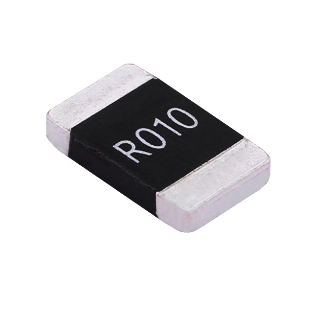
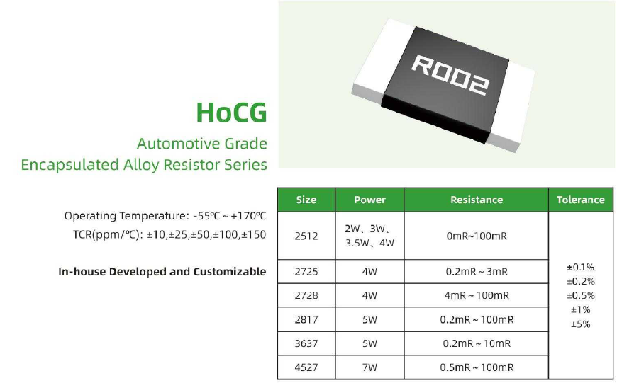
Facing the numerous issues caused by parasitic inductance, when selecting resistors, prioritize resistors with low parasitic inductance, such as Milliohm Electronic's proprietary alloy resistors. These resistors feature a compact internal structure, a short current path, and relatively low parasitic inductance. In PCB layout design, minimize the resistor leads to minimize the current loop area. Strategically plan the placement of resistors to avoid proximity to other components susceptible to interference. Adding decoupling capacitors can also suppress voltage fluctuations and resonance caused by parasitic inductance. For high-frequency, high-precision circuits with extremely stringent parasitic inductance requirements, custom low-parasitic inductance resistors can even be developed using specialized processes and materials. Milliohm's CG series sealed alloy resistors, as shown below, and other series, keep parasitic inductance below 3nH.

Although seemingly minor, parasitic inductance in resistor applications can have profound impacts on circuit performance. From attenuation and delay in high-frequency signal transmission to power integrity issues and the induction of resonance and oscillation, parasitic inductance acts like a hidden reef within circuits, constantly threatening stable operation. However, by gaining a deep understanding of its generation mechanisms and impacts, and implementing appropriate countermeasures, we can effectively tame this "invisible killer," ensuring stable and efficient circuit operation in a variety of complex application scenarios and providing a solid foundation for circuit reliability.
Note: If you would like to learn more about our products, solutions, or specific application scenarios, please feel free to contact our technical support team.
Notes on Reflow of Chip Resistors
Busbar - Not only for conductivity, but also for improving the heat dissipation system
Related Article
Key performance features: high power handling, ultra-low temperature drift, high overload withstand capability, low inductance at high frequency, and automotive-grade high reliability.
HoCG4527 Automotive Grade Molded Alloy Resistor
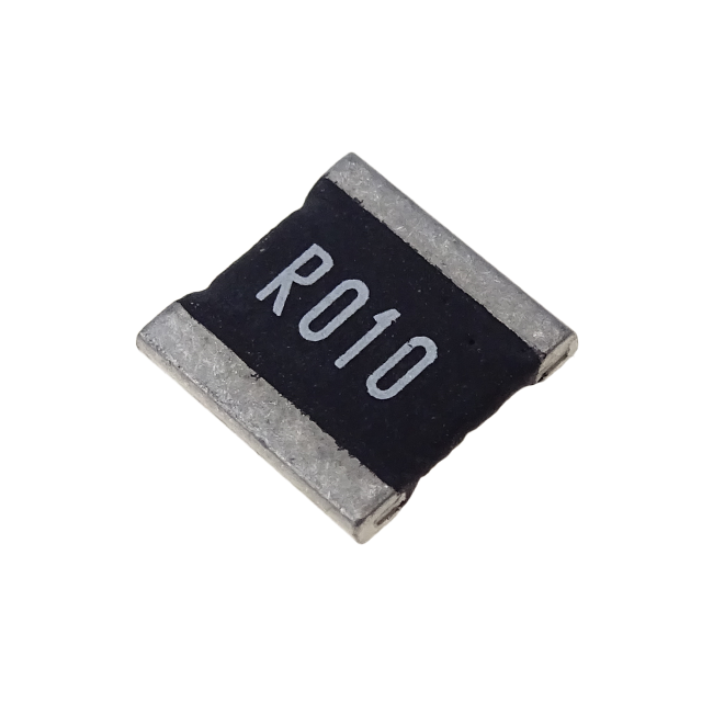
Key features: ultra-high current-carrying capability, ultra-high stability, ultra-low temperature drift, and low inductance at high frequency.
HoCG2728 Automotive Grade Molded Alloy Resistor

Alloy resistors, with their unique technical advantages—ultra-low resistance, low temperature drift, high power handling, low parasitic parameters, and strong pulse withstand capability—have become core components in current sensing, overload protection, and load matching circuits for EV charging stations.
Alloy Resistor Applications in New Energy