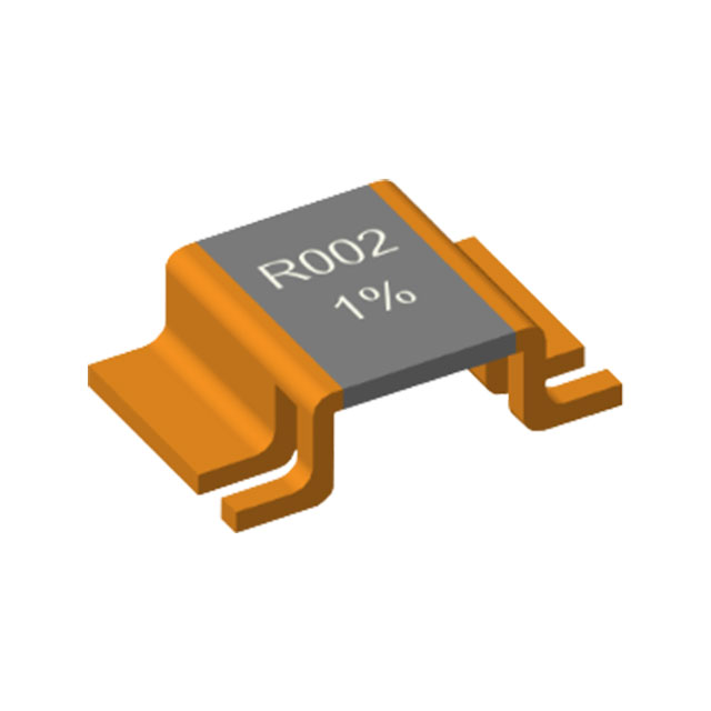
The application principle and specific method of bare alloy resistors in two or three wheeled vehicles
author: Milliohm Electronics
2025-06-30

1. Application Principle
- 1-1: Current Sampling and Battery Management
Principle: The exposed alloy resistor (such as manganese copper, constantan) is connected in series in the battery charging and discharging circuit, and the current is converted into a millivolt voltage signal through Ohm's law (V = I × R), which is transmitted to the controller (such as BMS). This signal is used to monitor the battery current in real time, realize charging and discharging control, power estimation and overcurrent protection.
Function:
Overcurrent protection: When the current exceeds the threshold, the controller cuts off the circuit to prevent the battery from over-discharging or the motor from overloading.
Power calculation: Estimate the remaining power by accumulating the current value (Coulomb counting method)
- 1-2. Temperature monitoring and protection
Principle: The heat generated by the alloy resistor is proportional to the square of the current (P = I²R). By detecting the temperature rise of the resistor (or combining with a temperature sensor), it is indirectly determined whether the system is overloaded. For example, when the temperature exceeds the safety threshold (such as 80°C), the controller reduces the output power
Advantage: The low temperature coefficient of the alloy resistor (TCR <50 ppm/°C) ensures that the sampling accuracy is not affected by temperature drift
- 1-3. Short circuit protection
Principle: When a short circuit occurs, the current increases sharply, and the voltage across the alloy resistor soars, triggering the controller's fast shutdown circuit (such as MOSFET drive), cutting off the main circuit within milliseconds to protect the battery and motor
2. Specific implementation methods
- 2-1: Model selection and parameter design
Material selection:
MnCu: low TCR (±15 ppm/℃), moderate cost, suitable for general-purpose vehicles.
Constantan (CuNi): strong corrosion resistance, suitable for humid environments (such as riding in rainy season)
Calculation example:
If the vehicle peak current is 50A and the target voltage drop is 50mV, the resistance value needs to be: R = V/I = 0.05V / 50A = 1 mΩ
Power margin: P = I²R = (50A)² × 0.001Ω = 2.5W → Select a resistor above 5W
- 2-2: Installation location and structural design
Installation location:
Battery output terminal: connected in series between the negative electrode of the battery and the controller, directly monitoring the total current 110.
Motor phase line: used for three-phase motor current balance detection (requires multiple resistors).
Mechanical fixation: copper bracket welding or bolt fastening is used to ensure low contact resistance. The resistor body needs to be exposed for heat dissipation and avoid closed space (>5mm away from other components).
PCB design: Kelvin connection (four-wire system) is used for sampling routing to separate the current path and voltage detection line to reduce errors
- 2-3: Signal processing circuit
Amplification circuit: The millivolt signal needs to be amplified 100–500 times by an op amp (such as LM358) and then input into the ADC pin of the MCU.
Example circuit: alloy resistor → low-pass filter (RC circuit) → differential amplifier → ADC.
Calibration method: adjust the amplification factor through adjustable resistors, or set the calibration coefficient in the software (such as a mapping table of measured current and ADC readings)
- 2-4: Heat dissipation and protection
Heat dissipation design: copper foil heat dissipation pads (area ≥ 100 mm²) are laid under the resistor.
When the power is > 5W, an aluminum heat sink is installed and thermal grease is applied.
Environmental protection: spray anti-oxidation coating (such as acrylic resin) to prevent rain and salt spray corrosion, and avoid installation in the tire splash area or low chassis position
3: Design points and precautions
3-1: Anti-interference design: The sampling line is far away from the motor drive line, and twisted pair or shielded line is used. Connect a 100nF capacitor in parallel to the input of the op amp to suppress high-frequency noise
3-2: Safety redundancy: The alloy resistor needs to withstand 2 times the peak current (for 5 seconds) to prevent damage from startup surge
3-3: Repair and replacement: Disable ordinary resistors: The TCR of carbon film resistors is too high (>200 ppm/℃), and temperature drift causes inaccurate control
3-4: Replacement principle: The resistance value, power and TCR must be matched, and copper wire cannot be used as a substitute
4. Technical advantages and limitations
✅ Low cost: more than 70% cheaper than the Hall sensor solution;
✅ Fast response: no hysteresis effect, suitable for transient current protection;
✅ Long life: alloy material is resistant to aging, life> 100,000 hours.
✅ Fast response: no hysteresis effect, suitable for transient current protection;
✅ Long life: alloy material is resistant to aging, life> 100,000 hours.
Limitations:
❌ High-voltage circuits need to be isolated (such as > 60V models);
❌ High power consumption in high current scenarios (such as > 100A models recommend using transformers)
❌ High-voltage circuits need to be isolated (such as > 60V models);
❌ High power consumption in high current scenarios (such as > 100A models recommend using transformers)
Bare alloy resistors have become core components for battery management and motor control in two- and three-wheeled vehicles through precise current sampling and fast protection mechanisms. When designing, it is necessary to comprehensively consider resistance accuracy, heat dissipation layout, and environmental adaptability, while combining software calibration to improve system reliability. In the future, as silicon carbide (SiC) devices become more popular, alloy resistors are expected to be integrated with smart fuses to achieve a more compact protection module

Understanding electrode materials - copper
The application principles and specific methods of constantan wire and manganese copper wire resistors in induction cookers
Related Article
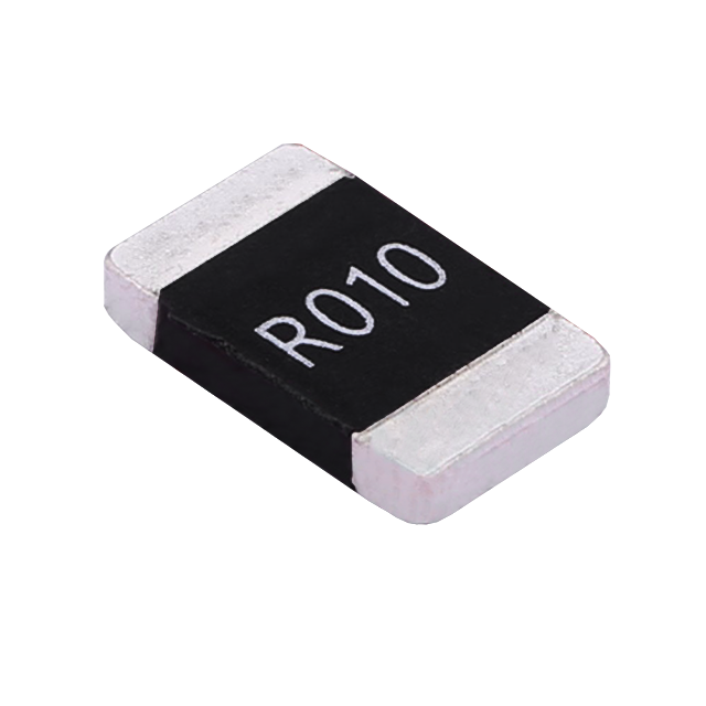
Key performance features: high power handling, ultra-low temperature drift, high overload withstand capability, low inductance at high frequency, and automotive-grade high reliability.
HoCG4527 Automotive Grade Molded Alloy Resistor
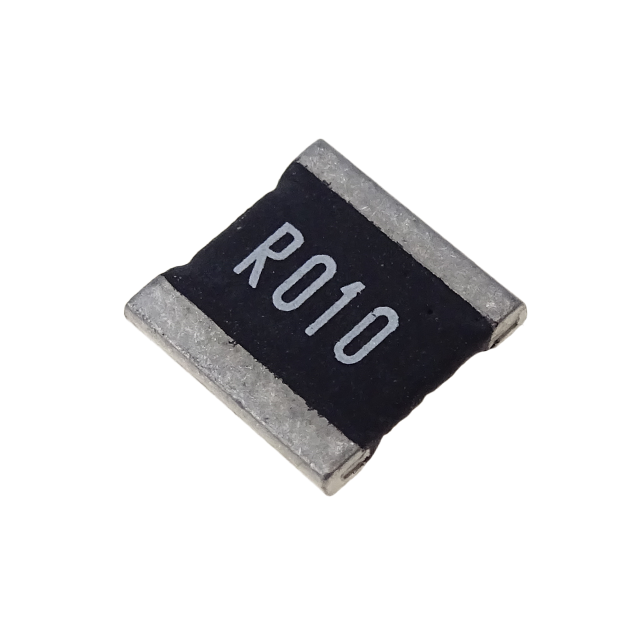
Key features: ultra-high current-carrying capability, ultra-high stability, ultra-low temperature drift, and low inductance at high frequency.
HoCG2728 Automotive Grade Molded Alloy Resistor

Alloy resistors, with their unique technical advantages—ultra-low resistance, low temperature drift, high power handling, low parasitic parameters, and strong pulse withstand capability—have become core components in current sensing, overload protection, and load matching circuits for EV charging stations.
Alloy Resistor Applications in New Energy