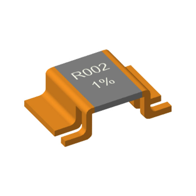
The application areas and methods for shunt resistors in inverters/photovoltaic/wind/hydro/hydrogen and instrumentation equipment
author: Milliohm Electronics
2025-05-26

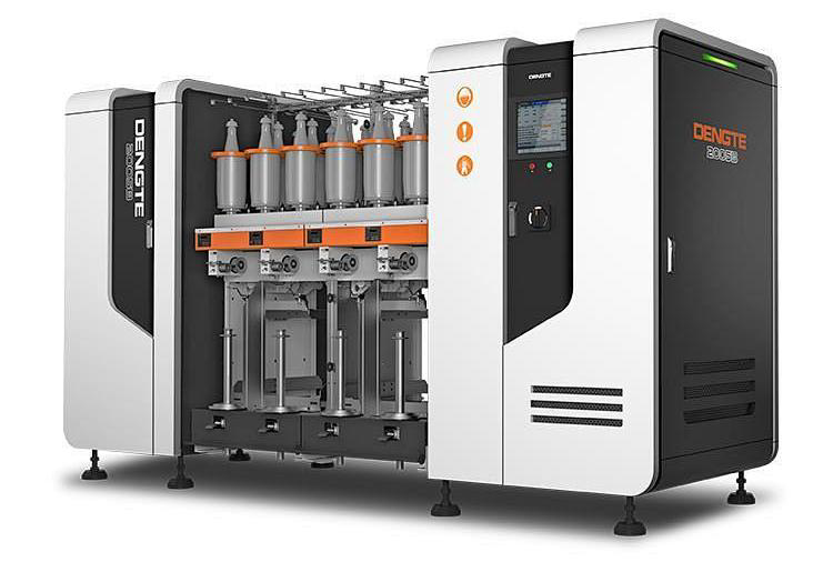
Instrumentation equipment
- High-precision measurement
Application: 10A range of digital multimeter (such as Fluke 87V)
Method: Use a four-wire manganese copper shunt (0.01Ω±0.1%) to eliminate lead error
Method: Use a four-wire manganese copper shunt (0.01Ω±0.1%) to eliminate lead error
- Industrial process control
Application: PLC analog input module (such as Siemens SM331).
Method: Convert 4-20mA signal to voltage and collect it through 24-bit ADC
Method: Convert 4-20mA signal to voltage and collect it through 24-bit ADC
- Battery testing equipment
Application: Charge and discharge tester (such as Chroma 17011).
Method: Multi-range shunt automatically switches, covering the range of μA to 100A
Method: Multi-range shunt automatically switches, covering the range of μA to 100A
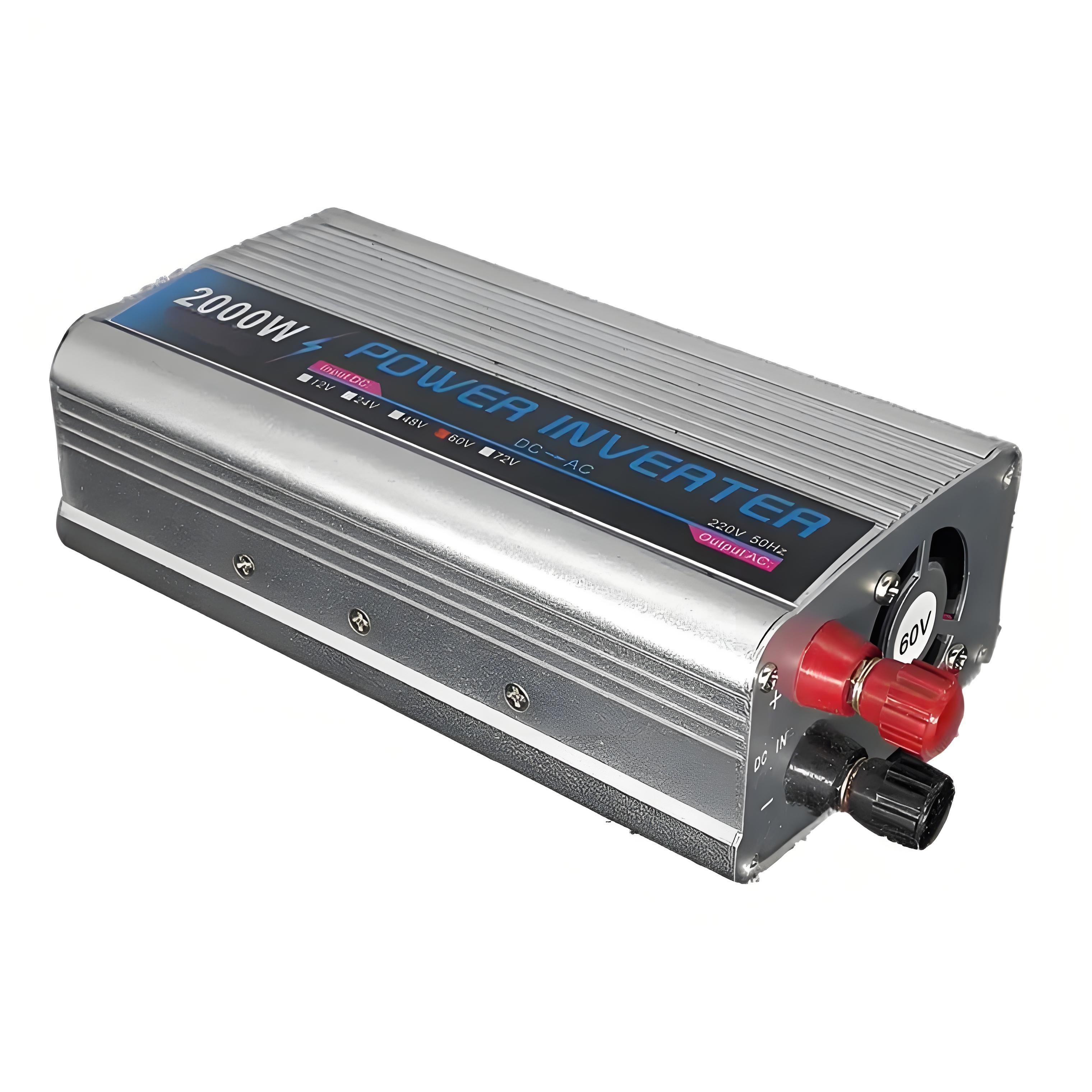
Inverter system
- DC bus current detection
Location: Connected to the DC input side, close to the capacitor or IGBT module.
Method: By measuring the voltage across the shunt, the input current is monitored in real time for overload protection and efficiency optimization.
Method: By measuring the voltage across the shunt, the input current is monitored in real time for overload protection and efficiency optimization.
- AC output current feedback
Location: Inverter output (L/N line)
Method: Cooperate with the PWM controller to adjust the switching frequency to ensure stable sine wave output.
Method: Cooperate with the PWM controller to adjust the switching frequency to ensure stable sine wave output.
- IGBT/MOSFET current protection
Location: Power device source/emitter.
Method: Detect instantaneous current, trigger short-circuit protection, and prevent device damage.
Method: Detect instantaneous current, trigger short-circuit protection, and prevent device damage.

Photovoltaic system
- MPPT controller
Location: between the output end of the photovoltaic array and the DC-DC converter
Method: combine the voltage sensor to calculate the power and dynamically adjust the working point to the maximum power output
Method: combine the voltage sensor to calculate the power and dynamically adjust the working point to the maximum power output
- Combiner box monitoring
Location: the negative circuit of each string of photovoltaic modules
Method: multi-channel shunts monitor the current of each branch and quickly locate the faulty string (such as shadowing)
Method: multi-channel shunts monitor the current of each branch and quickly locate the faulty string (such as shadowing)
- Grid-connected inverter
Location: output end of the inverter AC side
Method: ensure that the grid-connected current harmonics meet the standards (such as THD <5%)
Method: ensure that the grid-connected current harmonics meet the standards (such as THD <5%)

Wind energy system
- Generator side current detection
Location: Doubly fed asynchronous generator rotor circuit
Method: Control rotor current frequency to achieve variable speed constant frequency operation
Method: Control rotor current frequency to achieve variable speed constant frequency operation
- Converter DC link
Location: DC bus between rectifier and inverter
Method: Balance the energy flow between generator and grid to prevent bus voltage fluctuation
Method: Balance the energy flow between generator and grid to prevent bus voltage fluctuation
- Power supply monitoring of variable pitch system
Location: Variable pitch motor drive circuit
Method: Monitor motor current to ensure accurate blade angle adjustment
Method: Monitor motor current to ensure accurate blade angle adjustment

Hydrogen energy system
- Electrolyzer current control
Location: DC power input terminal of alkaline or PEM electrolyzer
Method: Accurately control kiloampere current (such as 1kA@2V) to improve hydrogen production efficiency
Method: Accurately control kiloampere current (such as 1kA@2V) to improve hydrogen production efficiency
- Fuel cell stack monitoring
Location: cathode/anode gas path of single cell in the stack
Method: Detect single cell current density to avoid local overload
Method: Detect single cell current density to avoid local overload
- Hydrogen station compressor drive
Location: DC side of motor drive inverter
Method: Real-time current limiting protection to prevent compressor overload
Method: Real-time current limiting protection to prevent compressor overload

Hydropower system
- Hydrogenerator output
Location: neutral point of generator stator winding.
Method: detect three-phase unbalanced current and protect winding insulation
Method: detect three-phase unbalanced current and protect winding insulation
- Speed governor excitation control
Location: exciter output circuit
Method: adjust excitation current to stabilize output voltage
Method: adjust excitation current to stabilize output voltage
- Grid-connected synchronization detection
Location: front side of circuit breaker grid-connected
Method: match grid phase to prevent impact current
Method: match grid phase to prevent impact current

Key design considerations
- Heat dissipation design: Water-cooled shunts are used for megawatt-level inverters to reduce temperature drift to below 50ppm/℃
- Signal processing: Instrumentation amplifiers (such as AD8421) are used to suppress common-mode noise and improve signal-to-noise ratio
- Resistance optimization: Milliohm-level shunts (such as 0.1mΩ/500A) are used for electrolyzers, and ohm-level shunts are used for instruments
- Material selection: Shunts for wind/photovoltaic power need to withstand temperature differences (-40℃~85℃), and hydrogen energy systems require explosion-proof packaging
Through the above applications, shunt resistors play a key role in improving system efficiency, ensuring safe operation, and achieving high-precision measurements. The actual selection needs to be weighed based on the current range, environmental conditions, and accuracy requirements.
The Application and functions of encapsulated alloy resistors in small and large household appliances
HoCG2512 Series Automotive Grade Encapsulated Alloy Resistor
Related Article
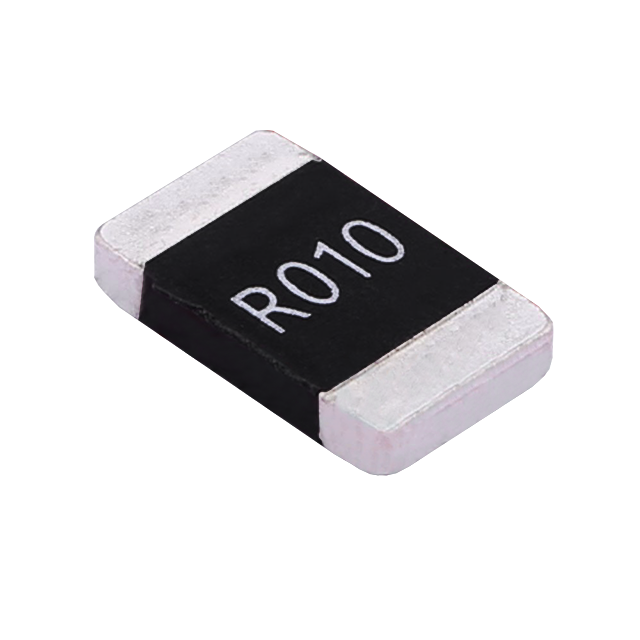
Key performance features: high power handling, ultra-low temperature drift, high overload withstand capability, low inductance at high frequency, and automotive-grade high reliability.
HoCG4527 Automotive Grade Molded Alloy Resistor
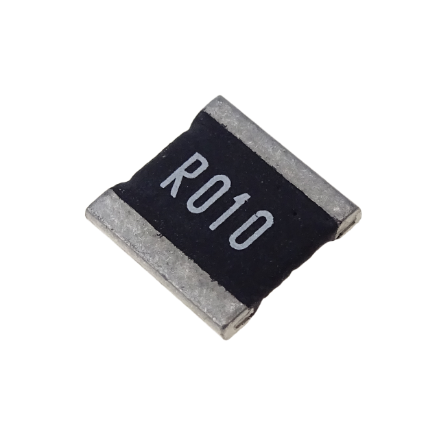
Key features: ultra-high current-carrying capability, ultra-high stability, ultra-low temperature drift, and low inductance at high frequency.
HoCG2728 Automotive Grade Molded Alloy Resistor

Alloy resistors, with their unique technical advantages—ultra-low resistance, low temperature drift, high power handling, low parasitic parameters, and strong pulse withstand capability—have become core components in current sensing, overload protection, and load matching circuits for EV charging stations.
Alloy Resistor Applications in New Energy