Improve the resistor pad layout to optimize current sensing accuracy
author: Milliohm Electronic
2025-08-14

I. Lead Layout Design for a Conventional Two-Terminal Package
To detect the voltage difference when current flows through a resistor, voltage terminals are required at both ends of the resistor. Voltage Terminal Lead Pattern.
As shown in the left figure below, if the voltage terminal is led out from the side of the electrode pad, the detected voltage difference will be the sum of the resistance of the low-resistance resistor and the copper pattern, resulting in inaccurate current detection or excessive error.
As shown in the right figure below, it is recommended to lead out from the inner center of the resistor's electrode pad. This is because the copper pattern on the circuit board has a small resistance, and this arrangement prevents voltage differences caused by this small resistance. The principle is a four-wire Kelvin connection, separating the main current path and the current sensing path to avoid the influence of lead resistance. Note that the current sensing leads should be close together, parallel, and symmetrical to eliminate differential-mode noise.

Even with a two-terminal sampling resistor, current detection is relatively accurate if the voltage terminals are correctly led out.
II. Four-Terminal Package Resistor Design
As shown in the figure below, the Kelvin principle is applied to the current sensing resistor itself. This connection requires four leads from a single resistor: two for normal operating current and two for measurement.
The advantage of a four-terminal package is the separate voltage sensing terminals, which reduces measurement errors caused by impedance at the terminals and allows for more accurate current detection.

A disadvantage of a four-terminal resistor is that the impedance RL formed between the voltage and current sensing terminals is larger than that of a two-terminal resistor. Therefore, for the same current flowing through a two-terminal resistor, the four-terminal resistor consumes slightly more power, as shown in Figure below. This also means that the resistor generates more heat. If the current in the project circuit is small, the heat generated can be ignored.

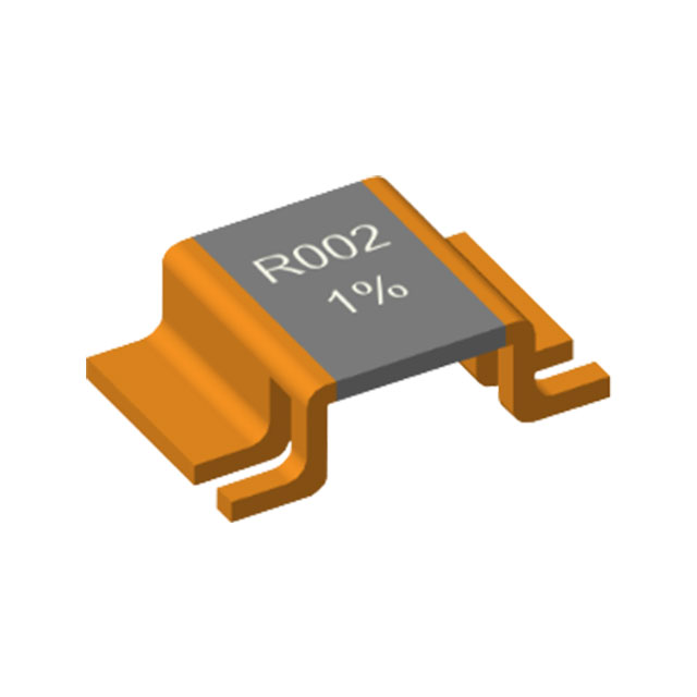
If the heat generation is significant, consider using the four-terminal package of the milliohm resistor VB series. As shown in the figure below, this design features a hollowed-out lead with curved ends, which provides improved heat dissipation while increasing detection accuracy. The hollowed-out lead also allows for PCB trace routing.

III.Kelvin Package Optimization—Six-Terminal Package Design
Except for four-terminal packages, when using extremely low-value resistors (in the milliohm or uΩ range), the physical location of the test point on the pad and the symmetry of the current flowing through the resistor become more significant. Every millimeter the current travels along the pad affects the effective resistance.
The LRS7998 milliohm resistor uses a six-terminal symmetrical pad, utilizing both sides of the pad to provide a more symmetrical system current path. This also moves the test point to a more central location. The test points are located at the center and ends of the pad, as shown in the figure below.

The layout of the sense traces also affects measurement accuracy. For higher accuracy, the sense voltage should be measured at the edge of the resistor. The layout shown below recommends using through-holes and routing the outer edge of the pad to another layer to avoid cutting into the main power layer

IV. Summary
As semiconductor advancements drive higher integration, current sensing technology continues to play a key role in energy efficiency management and safety. However, it still relies on the fundamental component, resistors. Factors such as resistor accuracy, power rating, temperature coefficient, heat dissipation, process, and quality all affect current sensing. Choosing the appropriate resistor for specific operating conditions is crucial. The resistors from Milliohm Electronic can provide technical information on product selection and support for product design. Please feel free to contact us
Note: The solutions described in this article may not be applicable to all resistors, depending on their material and size

Busbar - Not only for conductivity, but also for improving the heat dissipation system
Application of alloy resistors in frequency converters
Related Article
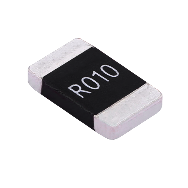
Key performance features: high power handling, ultra-low temperature drift, high overload withstand capability, low inductance at high frequency, and automotive-grade high reliability.
HoCG4527 Automotive Grade Molded Alloy Resistor
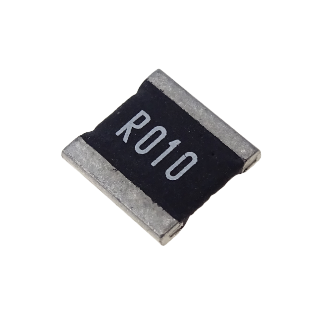
Key features: ultra-high current-carrying capability, ultra-high stability, ultra-low temperature drift, and low inductance at high frequency.
HoCG2728 Automotive Grade Molded Alloy Resistor

Alloy resistors, with their unique technical advantages—ultra-low resistance, low temperature drift, high power handling, low parasitic parameters, and strong pulse withstand capability—have become core components in current sensing, overload protection, and load matching circuits for EV charging stations.
Alloy Resistor Applications in New Energy