Derating principles for alloy resistors
author: Milliohm Electronic
2025-09-15

Alloy resistors are widely used in current sensing, power control, and precision measurement due to their unique performance advantages, such as low resistance, high precision, low temperature drift, and excellent heat dissipation. However, to fully utilize the performance of alloy resistors and ensure long-term stable and reliable circuit operation, derating is crucial.
I: Why is alloy resistor derating necessary?
According to Ohm's law, current passing through a resistor generates heat, causing the resistor's temperature to rise. If a resistor operates at or near its rated power for a long period of time, the excessive temperature will accelerate the aging of the internal materials, causing resistance drift and reduced precision, thereby affecting the normal operation of the entire circuit. Derating alloy resistors provides a safety margin, reducing heat generation during operation, extending the resistor's service life, and improving circuit reliability.
II: General Derating Principles
Rated value: The maximum allowable operating stress value for a component.
Stress: Loads such as electrical, thermal, mechanical, and environmental conditions that affect a component's failure rate.
Derating factor: The ratio of a component's operating stress to its rated stress, also known as the stress ratio.
Electrical stress: Voltage, current, and power applied to a component.
Temperature stress: The temperature of the component's operating environment.
Mechanical stress: Direct loads, pressure, shock, vibration, collision, and drops to which the component is subjected.
Environmental stress: Environmental factors other than temperature, such as dust, temperature, air pressure, salt spray, and corrosion, are present in the component's operating environment.
Time stress: The duration a component is subjected to stress (the longer the stress, the more susceptible it is to aging or failure).
III: Specific Principles for Derating Alloy Resistors
Resistors are primarily subject to power derating. Voltage derating is required for high-voltage applications, and current derating is also required for high-current environments.
① Power Derating Principles
Rated Power vs. Actual Power: The rated power of a resistor refers to the maximum power it can sustain stable operation without damage under specific environmental conditions (e.g., an ambient temperature of 25°C). However, in actual applications, due to fluctuations in ambient temperature and other factors in the circuit, the actual operating power of the resistor must be lower than its rated power. Generally speaking, it's recommended that the actual operating power of alloy resistors be controlled between 50% and 75% of the rated power. For example, for a 1W alloy resistor, its actual operating power should ideally not exceed 0.75W.
The Impact of Temperature on Power Derating: Ambient temperature is a key factor affecting the power derating of alloy resistors. As the ambient temperature rises, the heat dissipation capacity of the alloy resistor becomes limited, and its allowable operating power decreases accordingly. The interaction between these two parameters is represented by a load characteristic curve. Typically, a load power (power derating) curve is provided in the product data sheet.
As shown in the figure below, for example, the CG series milliohm resistor can withstand 100% of the rated power when the ambient temperature is below 70°C. When the ambient temperature reaches 100°C, the power it can withstand is derated to 75% of the rated power. In actual circuit design, the actual available power of the alloy resistor must be determined based on the actual operating temperature of the circuit and referenced by this curve. The horizontal axis represents the rated operating temperature of the resistor, and the vertical axis represents the percentage of power dissipated by the resistor.

As shown in the figure above, after temperatures exceed 70°C, the power dissipated by the resistor gradually decreases. The rate of this decrease depends on the resistor's heat dissipation capacity. If this curve is not explicitly provided in the component data sheet, the maximum temperature Tmax, power P, and thermal resistance R (unit: °C/W) are generally given. The decreasing slope is the inverse of the thermal resistance, from which the load characteristic curve can be derived.
② Voltage Derating Principle
Although alloy resistors are typically used in low-voltage, high-current applications, excessive voltage can also damage the resistor. The rated voltage of a resistor refers to the maximum voltage that can be applied across the resistor while ensuring normal operation and no damage. In actual applications, the voltage applied across the alloy resistor should be much lower than its rated voltage. For example, for an alloy resistor with a rated voltage of 100V, the actual operating voltage should ideally be kept below 60V-80V. This is because excessive voltage may cause internal corona discharge and other phenomena within the resistor, accelerating its aging and reducing its reliability.
③ Current Derating Principle
Alloy resistors generate heat when current flows through them. The higher the current, the more severe the heat. To ensure stable operation, the actual current flowing through the resistor should be lower than its rated current. Generally, it is recommended to control the actual current to around 70%-80% of the rated current. For example, if the rated current of an alloy resistor is 5A, the current flowing through it in the actual circuit should not exceed 4A. This effectively reduces the heat generated by the resistor and minimizes performance degradation or resistance drift caused by overheating.
IV: Precautions for Practical Applications
Accurately Assess Circuit Parameters: Before selecting an alloy resistor, it is important to accurately assess the circuit's operating voltage, current, power, and ambient temperature. Only by understanding these parameters can you select the appropriate alloy resistor according to the derating principle to ensure stable and reliable operation in the circuit.
Reference Datasheet: Different alloy resistors may have different performance parameters and derating curves. Therefore, when designing a circuit, it's crucial to carefully refer to the manufacturer's datasheet for the selected alloy resistor and follow the manufacturer's derating guidelines when selecting and applying it.
Consider heat dissipation design: To further reduce the operating temperature of alloy resistors and improve their reliability, heat dissipation should be fully considered in circuit design. Generally, this can be achieved by increasing the copper foil area on the PCB, providing heat dissipation holes, installing heat sinks, or installing cooling fans. This allows the resistor to better adapt to the operating environment while maintaining a derating rating.
In electronic circuit design, adhering to the derating principles for alloy resistors is crucial to ensuring long-term stable circuit operation. By properly derating the power, voltage, and current, and incorporating practical application considerations, the performance advantages of alloy resistors can be fully utilized, improving circuit reliability and stability, and providing a strong guarantee for high-quality electronic product design.

Note: For further information on products, solutions, or specific application scenarios, please feel free to contact technical support.
Application advantages and selection recommendations of alloy resistors in on-board chargers (OBC)
Notes on Reflow of Chip Resistors
Related Article
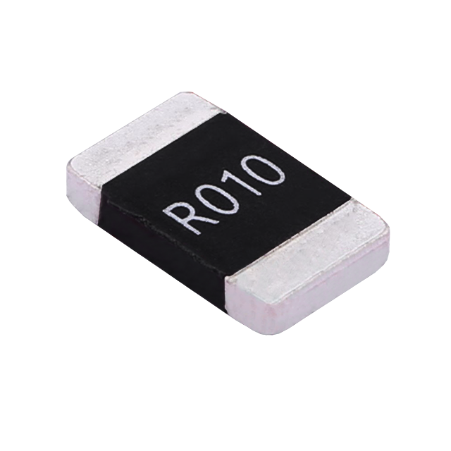
Key performance features: high power handling, ultra-low temperature drift, high overload withstand capability, low inductance at high frequency, and automotive-grade high reliability.
HoCG4527 Automotive Grade Molded Alloy Resistor
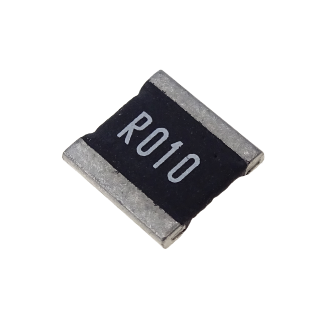
Key features: ultra-high current-carrying capability, ultra-high stability, ultra-low temperature drift, and low inductance at high frequency.
HoCG2728 Automotive Grade Molded Alloy Resistor

Alloy resistors, with their unique technical advantages—ultra-low resistance, low temperature drift, high power handling, low parasitic parameters, and strong pulse withstand capability—have become core components in current sensing, overload protection, and load matching circuits for EV charging stations.
Alloy Resistor Applications in New Energy