Built for harsh industrial environments: trapezoidal aluminum-housed resistors
I. Working Principle
The resistor works by dissipating electrical energy as heat (converting electrical energy into thermal energy). This enables three key functions:
-
Braking (Bleeding) Protection – It absorbs the regenerative energy generated when a motor slows down, preventing voltage spikes that could damage equipment.
-
Load Matching – It provides a stable load for the circuit, helping to maintain accurate parameters during device commissioning and operation.
-
Current Limiting & Voltage Dividing – It restricts current in the circuit or divides high voltage, protecting downstream components from damage
II. Physical Configuration
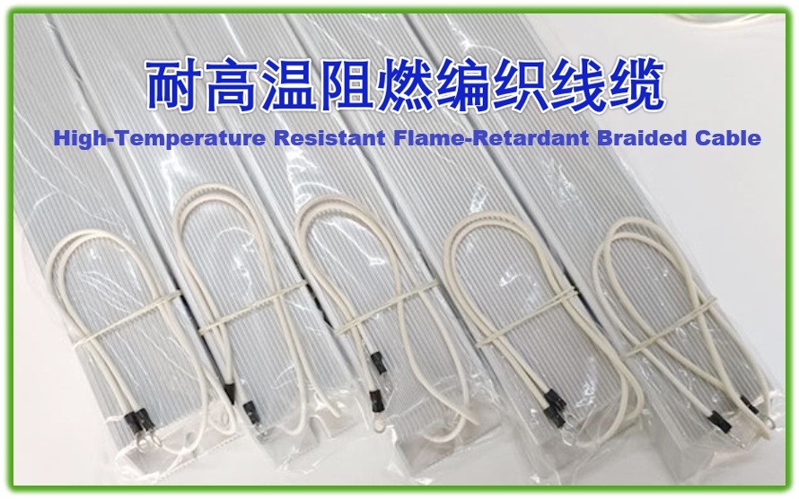
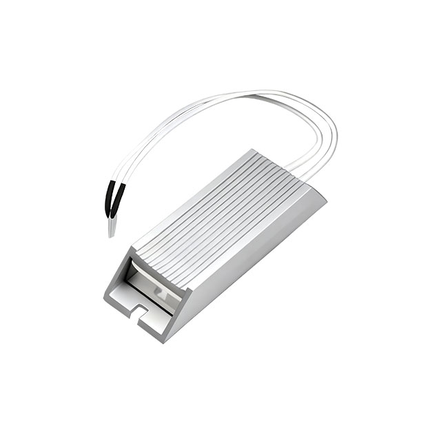
The cable is made of high-temperature resistant, flame-retardant braided material with a copper wire core for low current loss, and is tin-plated to resist long-term oxidation.
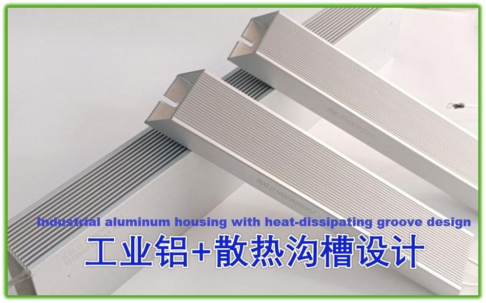
Constructed from industrial aluminum, this product features a stable structure and achieves a certain waterproof rating. Its well-designed cooling grooves improve heat dissipation efficiency
III. Core Advantages
-
High Protection Rating – IP54-rated, weather-resistant, dustproof and waterproof, suitable for complex industrial environments.
-
Wide Power Coverage – Full range from 40W to 2000W, meeting various power requirements.
-
Selectable Accuracy – Available in 1% and 5% tolerance grades for applications with different accuracy needs.
-
Excellent Heat Dissipation – Aluminum housing with an optional enhanced cooling design ensures stable operation in high-temperature environments.
-
Compliance & Certification – Certified to IATF 16949, RoHS, and REACH, meeting industry standards.
-
Flexible Installation – Available with 2-hole or 4-hole mounting options, and customizable lead wire lengths to fit various installation scenarios.
IV. Structural and Material Characteristics
Structural Design
-
Housing: Trapezoidal aluminum alloy housing (aluminum content ≥90%) with high-temperature anodized treatment to enhance heat dissipation efficiency.
-
Internal Encapsulation: Filled with flame-retardant inorganic material or silicone resin to ensure insulation and stability.
-
Resistor Element: Constantan / Nichrome alloy resistance wire wound on a ceramic core, offering high-temperature resistance and excellent stability.
Material Advantages
-
High-Temperature Performance: Withstands instantaneous high-temperature shocks.
-
Environmental Certification: Compliant with RoHS and lead-free standards.
-
Flame-Retardant Braided Sleeve: Resistant to physical stretching and high temperatures.
V. Production Process
-
Material Preparation ➡ Housing Machining Resistor ➡ Core Preparation ➡ Resistor Core Fixing ➡ Insulation Layer Coating ➡ Potting / Filling ➡ Performance Testing ➡ Reliability Verification ➡ Packing & Warehousing
-
Material Preparation: Industrial-grade aluminum and flame-retardant braided cables are used.
-
Housing Machining: The housing is formed into a trapezoidal structure through die-casting or stamping. The surface is then treated with high-temperature anodizing to enhance heat dissipation and corrosion resistance.
-
Resistor Element Preparation: Nichrome or constantan alloy resistance wire is wound around a mica sheet or ceramic core. Limit grooves are provided at the front and rear ends of the mica sheet to ensure uniform wire spacing (e.g., 0.5–2mm), preventing heat buildup and wire adhesion.
-
Resistor Element Fixing: The resistor core is secured inside the aluminum housing using methods such as snap-fitting, positioning grooves, or welding to ensure stability.
-
Insulation Treatment: The resistance wire is covered with insulating ceramic rings. Limit holes are provided at the four corners of the mica sheet to secure the leads. The inner wall of the aluminum alloy housing is coated with an insulating layer, and flame-retardant material is filled between the resistor core and the housing.
- Filling & Potting
① Thermal Conductive Medium: The interior is filled with quartz sand or silicone molding compound as a thermal conductive medium to enhance heat transfer efficiency.
② Sealing Process: High-insulation non-flammable filler is used for potting to ensure a tight bond between the resistor core and the housing.
- Performance Testing
① Electrical Parameters: Testing of resistance accuracy, withstand voltage, power matching, and insulation resistance.
② Environmental Adaptability: Validation of voltage endurance, moisture resistance, thermal shock, durability, etc.
- Reliability Verification
① Aging Test: Simulates long-term load operation to verify service life.
② Mechanical Strength Test: Includes vibration testing and shock testing to ensure stability in industrial environments.
- Packing & Warehousing
- Industrial Automation
① Inverter Braking Resistor – Absorbs motor regenerative energy to protect equipment.
② Crane / Elevator – Current limiting and dynamic braking to prevent overload.
③ Welding Machine / Servo System – Load resistor, braking resistor, voltage divider resistor to ensure stable start-stop of servo systems.
- Power Systems & Power Generation
① Solar Power – Inverter load resistors, combiner box current limiting resistors.
② Wind Power – Circuit loads and braking resistors in nacelles, resistant to vibration and extreme temperatures.
- Heavy Equipment
① Railway Systems – Braking resistors to ensure smooth and safe crane operation.
② Marine / Ships – Load and current limiting resistors for ship electrical systems, resistant to moisture and corrosion.
VII. Selection & Application Suggestions
- Power Margin
① Select a resistor with a power rating 1.5 times the actual power required. For example, if the circuit's calculated power is 100W, a resistor of 150W or higher should be selected.
② Additional derating is required in high-temperature environments. For instance, if the ambient temperature exceeds +70°C, the rated power must be adjusted according to the power-temperature curve.
- Voltage Limitation
① The maximum working voltage must satisfy the lower value between the rated power limit and the material's withstand voltage.
- Temperature & Vibration
① The operating temperature range is typically -55°C to +270°C. In high-temperature environments (e.g., electric heating equipment), models with low temperature coefficient (40–400 ppm/°C) are recommended for precision control applications.
② Vibration resistance must meet 1.5g acceleration, suitable for applications with frequent vibration such as elevators and ships.
VIII. Target Customer Base
- Direct Customers : Equipment Manufacturers & Electrical Panel Builders / System Integrators
- Indirect Customers : End-user Maintenance Departments & Design Institutes / Engineers
- Key Focus : Customers with demanding requirements for high power, harsh environments, and high reliability — typically found in new energy, heavy equipment, and specialized industrial sectors

Optimization strategy for current transmission and thermal management
Rated Power and Maximum Power for Shunts: In-Depth Analysis of Key Determining Factors
Related Article