Alloy Resistor: The Current Sentinel Guarding Battery Safety
author: Milliohm Electronics
2025-11-21
I. Precise Current Detector
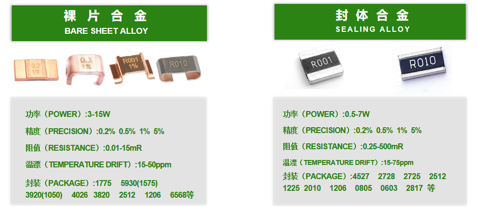
How to accurately sense current pulsations and prevent "crashes" caused by overload? The alloy resistors developed by Millio Electronics, with their milliohm-level resistance, ±0.001% accuracy, and ±1~5ppm/℃ low-temperature drift, become the "nerve endings" of the battery system.
II. Application Principle: A Precision Scale for Current
① Practical Application of Ohm's Law
The working principle of alloy resistors in battery systems directly points to the core of circuit theory—Ohm's Law (V=IR). By connecting a precisely valued resistor in series in the current path and measuring the voltage drop across it, the current magnitude can be deduced.
Advantages of Milliohm-level Resistance: Power batteries often operate at hundreds of amperes; excessive resistance leads to power loss and heat generation (P=I²R). Taking an 800A system in a new energy vehicle as an example, using a 0.1mΩ alloy resistor results in a power consumption of only 64W; if a 1mΩ ordinary resistor is used, the loss increases dramatically to 640W, enough to burn out the circuit.
Advantages of Four-Terminal Design: Eliminating Lead Resistance Errors. As shown in the figure below, the voltage detection terminal of the HoVB series alloy resistor is separated from the current path, reducing the measurement error to below 0.02%, which is crucial for estimating the SOC (State of Charge) of lithium batteries.

② Four Core Advantages: Compared to traditional aluminum-based resistors, alloy resistors exhibit significant advantages in battery applications:
Low Temperature Crop Ratio (TCR): The TCR of the Millio Electronics CG series reaches ±10ppm/℃, while ordinary resistors have a temperature drift of ±200ppm/℃, which can lead to significant errors in power display during winter.
Power Density: The Millio Electronics 5930 alloy resistor measures only 15.2×7.6mm, yet carries 15W of power, five times that of ordinary resistors.
High Precision: Laser-corrected resistor technology achieves ±0.01% accuracy, ensuring a coulomb measurement error of <1%.
Low Inductance: The three-dimensional alloy structure reduces parasitic inductance to ≤3nH, avoiding signal oscillations during high-frequency charging and discharging.
III. Application Cases: Guardians of Battery Safety
① New Energy Vehicle BMS System
The Tesla Model 3 battery pack uses 96 alloy resistors to construct a distributed detection network.
Cell-level monitoring: Every 3 parallel cells are connected in series with a 0.5mΩ resistor to monitor micro-short circuits with an accuracy of ±0.5%.
Thermal management linkage: When the resistor temperature rise exceeds the limit, the liquid cooling system is immediately triggered to cool it down.
② Home Energy Storage System
A leading manufacturer's 20kWh energy storage cabinet encountered a pain point: the traditional resistors reached a temperature rise of 80℃ under a continuous current of 50A, causing the power output to "jump". The upgrade solution is as follows:
A leading manufacturer's 20kWh energy storage cabinet encountered a pain point: the traditional resistors reached a temperature rise of 80℃ under a continuous current of 50A, causing the power output to "jump". The upgrade solution is as follows:
Parallel current sharing technology: 4 3920 alloy resistors (8W/0.25mΩ) are connected in parallel.
Temperature suppression: Copper substrate + thermal grease + air duct, ensuring a temperature rise of ≤35℃ under 100A conditions.
Improved accuracy: SOC estimation error is reduced from 5% to 0.5%, resulting in an annual electricity bill difference of over 2000 yuan.
IV. Selection Method: Five-Dimensional Decision Model
① Resistance and Power Calculation
Basic Formula: R = V/I, where V is recommended to be 10-50mV (signal-to-noise ratio balance) Power Budget: P≥I²×R×1.5 (safety margin) Example: For a 100A continuous current system, select V=50mV → R=0.5mΩ → P=100²×0.0005=5W → Select a resistor of 7W or higher.
Basic Formula: R = V/I, where V is recommended to be 10-50mV (signal-to-noise ratio balance) Power Budget: P≥I²×R×1.5 (safety margin) Example: For a 100A continuous current system, select V=50mV → R=0.5mΩ → P=100²×0.0005=5W → Select a resistor of 7W or higher.
② Temperature Drift Coefficient Selection: The temperature drift coefficient is based on the actual temperature rise of the product.
③ Package Size Balance
| Package | Dimension | Power | Resistance | Typical application scenarios |
| 1206 | 3.2x1.6 | 1W | 0.5-100mΩ | Laptop battery pack |
| 2512 | 6.4x3.2 | 3W | 0.2-500mΩ | Home energy storage BMS |
| 3920 | 10.0x5.2 | 7W | 0.1-5mΩ | New energy vehicle main circuit |
④ Automotive-Grade Certification Requirements
The power battery must meet the following requirements: AEC-Q200 certification: Pass a 1000-hour high-temperature storage test at 170℃. Mechanical strength: Withstand 50G mechanical impact to prevent vehicle vibration failure.
The power battery must meet the following requirements: AEC-Q200 certification: Pass a 1000-hour high-temperature storage test at 170℃. Mechanical strength: Withstand 50G mechanical impact to prevent vehicle vibration failure.
⑤ Reliability Design Recommendations
Enhanced heat dissipation: Prioritize copper electrode resistors (thermal conductivity 401W/mK), PCB copper area ≥ 3 times the resistor's projected area.
Layout recommendations: Voltage sensing traces should have equal length differential pairs and be kept away from interference sources such as inductors/transformers.
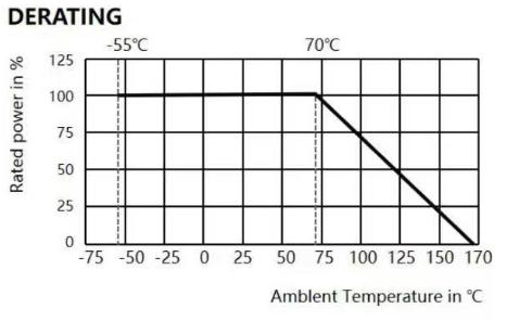
Derating curve: Refer to the manufacturer's temperature-power curve (Figure 3). Derating is required in environments up to 70℃.
Note: If you would like to learn more about our products or solutions, or their application in specific scenarios, please feel free to contact our technical support.
Application Principles and Scenarios of Alloy Resistors in On-Board Chargers (OBC)
Differences in resistance between FeCrAl and Kama alloy
Related Article
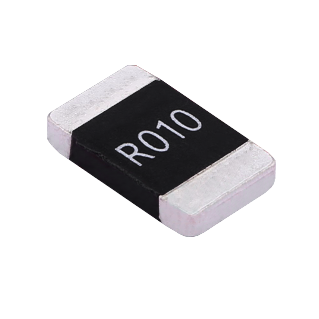
Key performance features: high power handling, ultra-low temperature drift, high overload withstand capability, low inductance at high frequency, and automotive-grade high reliability.
HoCG4527 Automotive Grade Molded Alloy Resistor
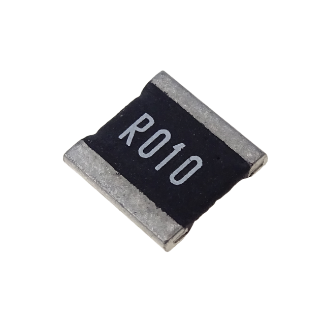
Key features: ultra-high current-carrying capability, ultra-high stability, ultra-low temperature drift, and low inductance at high frequency.
HoCG2728 Automotive Grade Molded Alloy Resistor

Alloy resistors, with their unique technical advantages—ultra-low resistance, low temperature drift, high power handling, low parasitic parameters, and strong pulse withstand capability—have become core components in current sensing, overload protection, and load matching circuits for EV charging stations.
Alloy Resistor Applications in New Energy