Reliability test: temperature coefficient
author: Milliohm Electronic
2025-08-13

1.Units of temperature coefficient and meanings of positive and negative temperature coefficients
① The most common units are ppm/°C (parts per million per degree Celsius) or ppm/K.
1 ppm/°C = 0.0001 %/°C. This means that for every 1°C change in temperature, the resistance changes by one millionth of its value.
1 ppm/°C = 0.0001 %/°C. This means that for every 1°C change in temperature, the resistance changes by one millionth of its value.
②Positive temperature coefficient (PTC): α > 0. This indicates that the resistance increases with increasing temperature.
Negative temperature coefficient (NTC): α < 0. Indicates that resistance decreases as temperature increases.
Negative temperature coefficient (NTC): α < 0. Indicates that resistance decreases as temperature increases.
Tips: Passive components (resistors, capacitors, and inductors) also have temperature coefficients other than resistance.
The temperature coefficient of capacitance (TCC) describes how much the capacitance value changes with temperature.
The temperature coefficient of inductance (TCI) describes how much the inductance value changes with temperature.
The temperature coefficient of capacitance (TCC) describes how much the capacitance value changes with temperature.
The temperature coefficient of inductance (TCI) describes how much the inductance value changes with temperature.
2.The impact of resistance temperature coefficient on products
① Resistor Drift: Any change in temperature causes the actual resistance of a resistor to deviate from its nominal value (measured at room temperature). This is a major source of error in circuits that require precise resistance values.
②Impacts in Practical Applications
②-1 Degraded Accuracy: In precision measuring instruments (multimeters, oscilloscope probes), medical devices, test equipment, and high-precision data converters (ADCs/DACs), small drifts in resistor values can directly translate into measurement or output errors. These applications require extremely low TCRs (e.g., <5 ppm/°C or even <1 ppm/°C), and often use precision alloy resistors, precision wirewound resistors, or low-drift thin-film resistors.
②-2 Stability Issues: In applications requiring long-term output stability, such as power supplies, voltage references, and clock circuits, drift caused by resistor TCR can lead to unstable output voltage or frequency.
②-3 Matching Requirements: In differential amplifiers, instrumentation amplifiers, and bridge circuits, resistor pairs at critical locations require extremely low TCRs and good TCR matching.
②-4 Nonlinearity in Power Applications: In high-power resistor applications, self-heating of the resistor causes a temperature increase. If the TCR is high, the resistance value will change significantly (usually increasing), which can result in reduced current or inaccurate power calculations, affecting system efficiency or control accuracy.
Tips: High TCR also has some specific applications, such as temperature sensing, temperature compensation, overheating protection, etc.
3.How to calculate the temperature coefficient of resistance (TCR)
①TCR calculation formula:

R1: Resistance at base temperature
T1: Base temperature
R2: Resistance at any temperature
T2: Any temperature
T1: Base temperature
R2: Resistance at any temperature
T2: Any temperature
② Example 1: A resistor measured at 25°C is 10mR. When the temperature rises to 85°C, the resistance is again measured as 10.06mR. What is the TCR of this resistor?
TCR (ppm/°C) = (R2-R1)/(R1 × (T2-T1)) × 1,000,000 →
TCR = (10.06-10)/(10 × (85-25)) × 1,000,000
TCR = 100ppm/°C
③ Example 2: For a resistor with a TCR of 100ppm/°C, what is the rate of change in resistance from a base temperature of 25°C to 85°C?
Temperature coefficient of resistance (ppm/°C) = (R2-R1)/(R1 × (T2-T1)) × 1,000,000 →
100 (ppm/°C) = (R2-R1)/R1 ÷ (85-25) × 1,000,000
(R2-R1)/R1 = 0.006 = 0.6%
Temperature coefficient of resistance (ppm/°C) = (R2-R1)/(R1 × (T2-T1)) × 1,000,000 →
100 (ppm/°C) = (R2-R1)/R1 ÷ (85-25) × 1,000,000
(R2-R1)/R1 = 0.006 = 0.6%
4.How to measure the temperature coefficient of resistance (TCR)
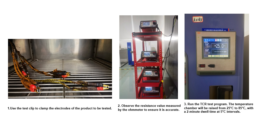
Record the resistance value every 5°C. Enter the recorded resistance value into the TCR test table and calculate the TCR value.
5. TCR levels of common products
| Series | Part Number | TCR Standard | TCR Test Result |
| Bare Alloy Resistor | HoLRS1050-0.5mR-1% | ±25ppm~±100ppm | 50ppm |
| HoLRS1050-1mR-1%-K | -15ppm | ||
| HoLRS1575-0.2mR-1% | ±25ppm~±100ppm | 70ppm | |
| HoLRS1575-2mR-1%-K | 20ppm | ||
| Encapsulated Alloy Resistor | HoCG2512-3-R001-F-4 | ±50ppm | 20ppm |
| HoCG2512-3-R005-F-4 | -20ppm |

6.Temperature rise of alloy resistors
① What is temperature rise?
①-1 Definition: Temperature rise refers to the increase in resistor body temperature relative to the ambient temperature when powered. The unit is usually degrees Celsius (°C).
①-2 Temperature rise = Resistor body temperature - Ambient temperature
①-3 Temperature rise rate = (Resistor body temperature - Ambient temperature) / Power dissipation
①-4 Key Concept: This reflects the degree of heat generated by a resistor during operation due to its own power dissipation.
①-2 Temperature rise = Resistor body temperature - Ambient temperature
①-3 Temperature rise rate = (Resistor body temperature - Ambient temperature) / Power dissipation
①-4 Key Concept: This reflects the degree of heat generated by a resistor during operation due to its own power dissipation.
② Why does temperature rise occur?
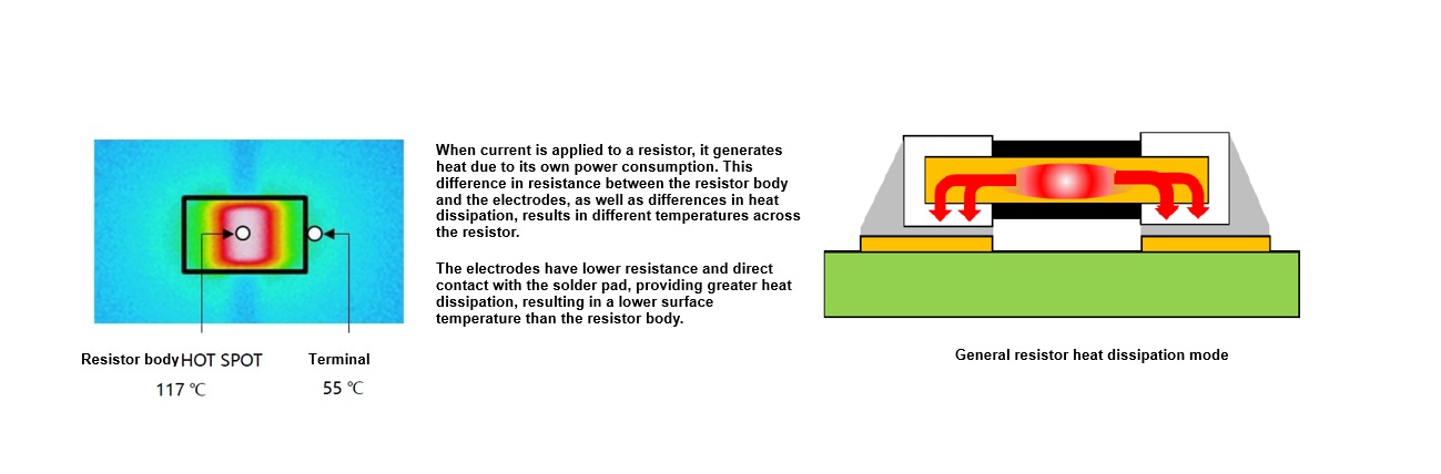
Basic Principle: When current flows through a resistor, according to Joule's law, electrical energy is converted into heat. This is an inherent characteristic of resistors.
Power dissipation (P) = I² * R or P = V² / R or P = V * I. This power dissipation, P, is the fundamental cause of resistor heating.
Power dissipation (P) = I² * R or P = V² / R or P = V * I. This power dissipation, P, is the fundamental cause of resistor heating.
③ Key factors affecting temperature rise
③-1 Power consumption: This is the most direct and primary factor. The greater the power consumption, the more heat generated, and naturally, the higher the temperature rise. Power consumption is determined by the current flowing through the resistor and the resistance value itself.
③-2 Resistor thermal resistance: Thermal resistance indicates the resistance to heat transfer from the resistor's core to the surrounding environment. Measured in C/W, it measures the resistor's heat dissipation capabilities.
③-3 Ambient temperature: At the same power consumption, higher ambient temperatures increase the resistor's body temperature (due to a higher starting temperature). The temperature rise itself may vary slightly, but absolute temperature is the more important design metric (usually with a maximum operating temperature limit).
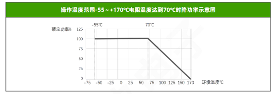
③-4 Resistor Size and Package: Generally speaking, under the same power consumption and heat dissipation conditions, larger resistors have greater surface area, better heat dissipation, and relatively lower temperature rise. Resistors with smaller packages will have higher temperature rises at the same power consumption.
③-5 Thermal Conductivity of the Resistor Material: The better the thermal conductivity of the material itself (such as certain metal alloy substrates), the lower the internal thermal resistance, making it easier for heat to transfer to the surface.
③-6 Protective Coating/Potting: Coatings or potting compounds with poor thermal conductivity will hinder heat dissipation, increasing thermal resistance and temperature rise.
④ What are the effects of excessive temperature rise?
④-1 Accelerated Material Aging: Continuous high temperatures accelerate the aging process of resistor materials, protective layers, solder, and PCB materials.
④-2 Shortened Lifespan: The lifespan of electronic components generally follows the "10-degree rule" (Arrhenius equation), meaning that for every 10°C increase in operating temperature, the lifespan is approximately halved. Excessive temperature rise can significantly reduce the life expectancy of resistors and surrounding components.
④-3 Resistance Drift: Although alloy resistors have a low TCR, extreme high temperatures can still cause irreversible resistance drift, affecting circuit accuracy (especially in precision current sensing).
④-4 Reduced Reliability: Increases the risk of open circuits, short circuits, or other failures.
④-5 Thermal Stress: Due to different thermal expansion coefficients between the resistor body, solder joints, and PCB materials, excessive temperature rise and temperature cycling can generate thermal stress, potentially causing solder joint cracking or resistor damage.
④-6 Impact on Neighboring Components: A heated resistor heats the surrounding air and PCB area, potentially causing nearby temperature-sensitive components (such as semiconductors and electrolytic capacitors) to exceed their safe operating temperature range.
④-7 Safety Issues: In extreme cases, excessive temperatures could ignite nearby flammable materials or cause burns (although the resistor itself does not typically catch fire).
⑤ How to measure the temperature rise of a resistor?

Application of alloy resistors in frequency converters
Key Precautions for Using Surface-Mount Alloy Resistors
Related Article
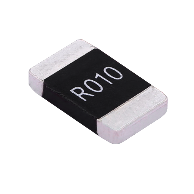
Key performance features: high power handling, ultra-low temperature drift, high overload withstand capability, low inductance at high frequency, and automotive-grade high reliability.
HoCG4527 Automotive Grade Molded Alloy Resistor
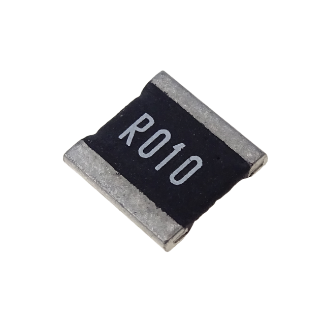
Key features: ultra-high current-carrying capability, ultra-high stability, ultra-low temperature drift, and low inductance at high frequency.
HoCG2728 Automotive Grade Molded Alloy Resistor

Alloy resistors, with their unique technical advantages—ultra-low resistance, low temperature drift, high power handling, low parasitic parameters, and strong pulse withstand capability—have become core components in current sensing, overload protection, and load matching circuits for EV charging stations.
Alloy Resistor Applications in New Energy