Application of alloy resistors in frequency converters
author: Milliohm Electronic
2025-08-14
I. Overview of the Operating Principle of a Frequency Converter
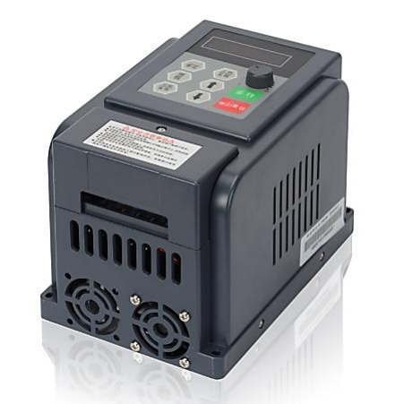
A frequency converter (VFD) is an energy control device that converts industrial frequency power to another frequency using the switching function of power semiconductor devices. Its core function is to precisely regulate parameters such as motor speed and torque through rectification, filtering, and inversion.
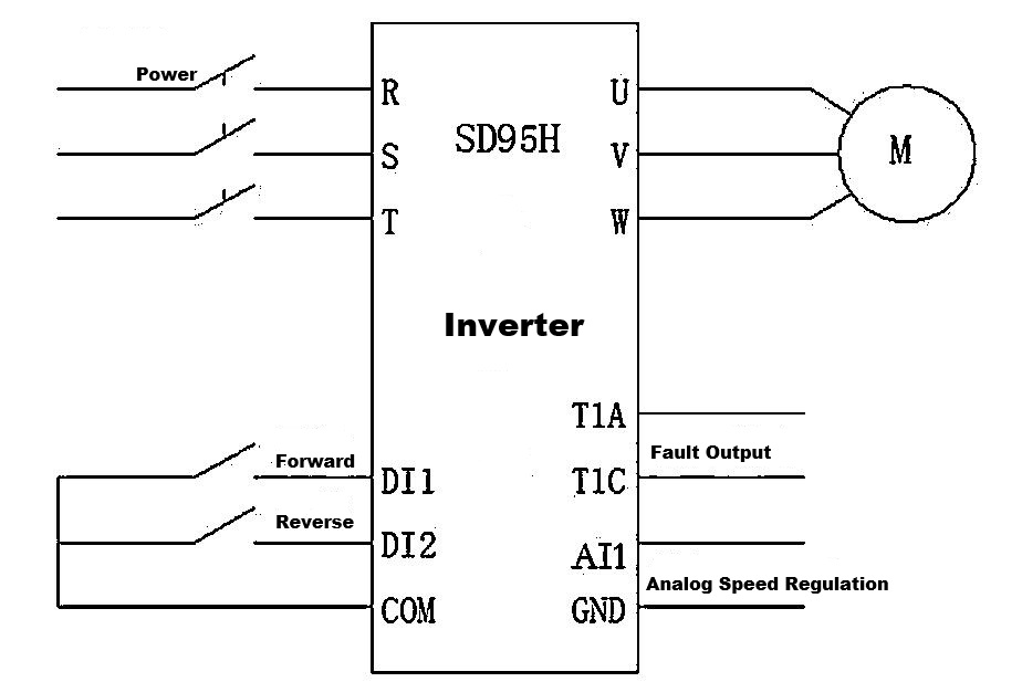
In industrial automation, home appliances, and new energy, VFDs are widely used to drive and control equipment such as fans, pumps, elevators, and air conditioners. During operation, VFDs convert electrical energy between AC and DC, generating large current and voltage fluctuations in the circuit. Consequently, they place stringent requirements on the performance of the resistor components within the circuit.
II. Alloy Resistor Characteristic Matching
Alloy resistors are made from a variety of metal alloys and feature high precision, low temperature coefficient, high power handling capacity, and excellent heat dissipation.
The high precision ensures precise monitoring and control of current and voltage in complex circuit environments. The low temperature coefficient means minimal change in resistance with temperature fluctuations, maintaining stable circuit parameters. The high
power handling capacity and excellent heat dissipation allow them to withstand the high currents and heat generated during inverter operation, ensuring stable operation of the resistor itself and the entire circuit system.
III. Specific Applications of Alloy Resistors in Inverters
①Startup Current Limiting Applications
At the instant an inverter starts, the filter capacitors need to rapidly charge, generating a large inrush current. If not limited, this can damage components such as the rectifier diodes and filter capacitors. In these situations, alloy resistors are connected to the circuit as current limiting resistors. During the initial startup phase, the alloy resistors use their resistance to limit the charging current, allowing the filter capacitors to charge smoothly.
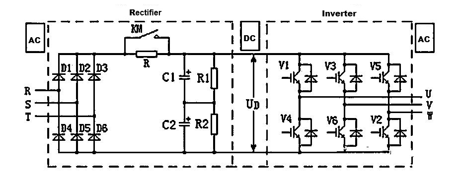
Above diagram, a resistor is connected in parallel across filter capacitors C1 and C2 to keep the voltages across the two capacitors roughly equal, preventing damage during operation. Furthermore, a resistor R and a pair of contactor contacts KM are connected between the rectifier bridge and the filter capacitors. This is because when the inverter is first connected to power, the voltage across the filter capacitors is 0V, while the peak rectified voltage at a 380V power supply is 537V. This creates a significant charging surge current at the instant the power is turned on, potentially damaging the rectifier diodes
Furthermore, a filter capacitor with a zero terminal voltage will cause the rectified voltage to drop to 0V instantaneously, causing interference to the power supply network. To address this issue, a current-limiting resistor R is connected between the rectifier bridge and the filter capacitors to limit the charging current of the filter capacitors to within an acceptable range. However, if the current-limiting resistor R is always connected in the circuit, its voltage drop will affect the inverter's output voltage and reduce its energy conversion efficiency. Therefore, after the filter capacitors are fully charged, the contactor KM short-circuits the current-limiting resistor R, shutting the inverter down
② Overcurrent Protection Application
During inverter operation, when a sudden change in motor load, a short circuit, or other fault causes an abnormal increase in current in the circuit, rapid detection and protective measures are required. Alloy resistors can be used as overcurrent detection elements, connected in series in the main circuit. Their high precision allows them to accurately convert current fluctuations into voltage signals. When the current exceeds the set threshold, this voltage signal triggers the overcurrent protection circuit, causing the inverter to quickly cut off output, thereby protecting the motor and other circuit components from damage caused by excessive current.
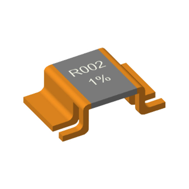
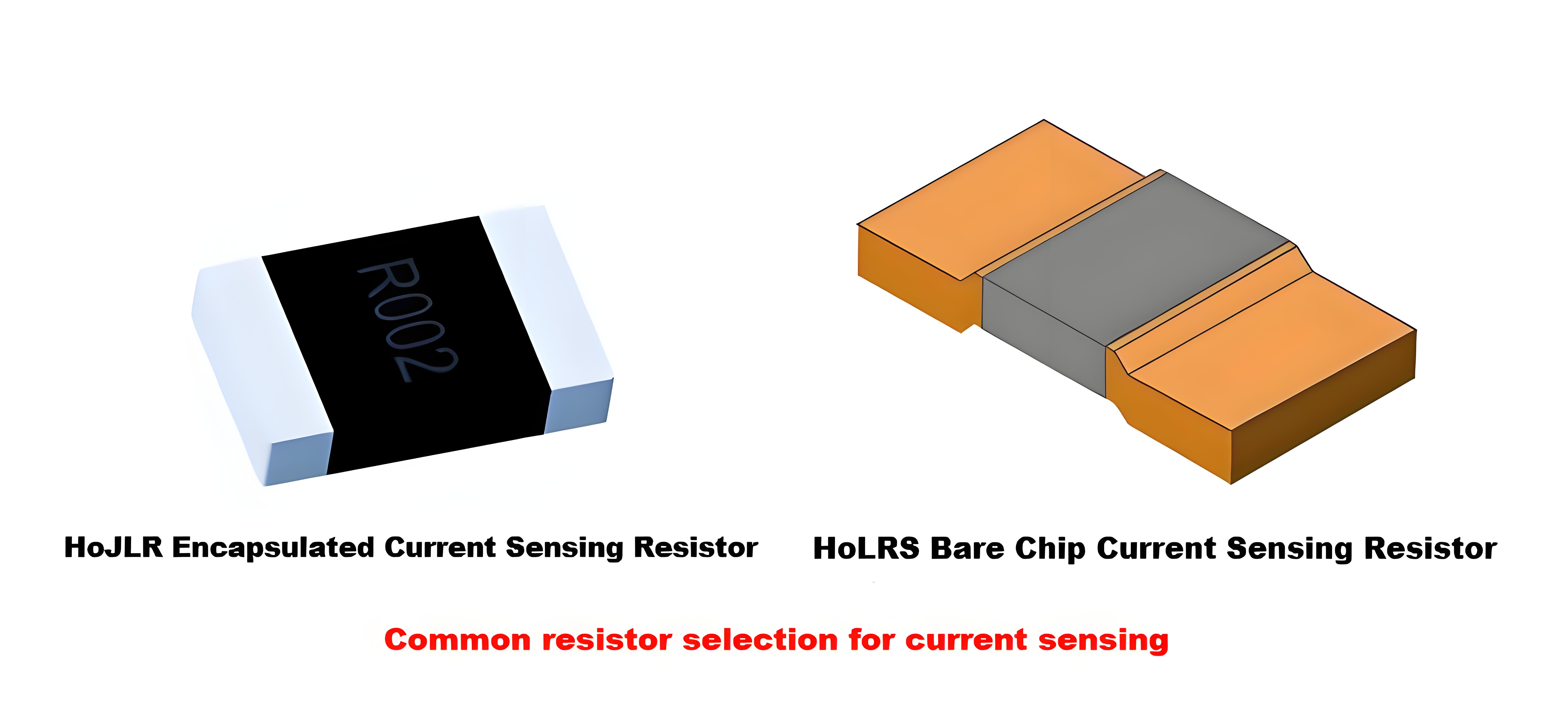
Furthermore, the stable performance of alloy resistors ensures accurate and reliable overcurrent detection under various operating conditions. The following are commonly used bare die and encapsulated alloy resistors for current detection and protection.

③ Voltage Sampling and Feedback Control Application
To achieve precise output voltage control, the inverter requires real-time voltage signal acquisition and feedback to the control system. Alloy resistors, leveraging their high precision and low temperature coefficient, form a voltage divider circuit to sample the inverter's output voltage. By selecting appropriate resistor values, the high-voltage signal is converted into a low-voltage signal suitable for the control system, ensuring the accuracy and stability of the sampled voltage. The control system adjusts the inverter output in real time based on the deviation between the sampled voltage and the set value, achieving closed-loop control of the output voltage. This ensures a stable and accurate inverter output voltage that meets load operating requirements.
④ Braking Resistor Application
When the inverter-driven motor needs to rapidly decelerate or stop, the motor generates regenerative energy, which is fed back into the DC bus and causes the DC bus voltage to increase. If not promptly addressed, this excessive voltage can damage the inverter's internal components. The alloy resistor acts as a braking resistor connected to the DC bus. When the DC bus voltage exceeds the set value, the braking unit conducts, dissipating the regenerative energy generated by the motor as heat and maintaining the DC bus voltage within a safe range. Alloy resistors' high power carrying capacity and excellent heat dissipation performance enable them to quickly and stably dissipate regenerative energy, ensuring safe operation of inverters and motors.
IV. Summary
With their high precision, low temperature coefficient, high power carrying capacity, and excellent heat dissipation, alloy resistors play an irreplaceable role in key aspects of inverters, including startup current limiting, overcurrent protection, voltage sampling and feedback control, and braking. By effectively utilizing the characteristics of alloy resistors, inverters can achieve stable and reliable operation, improving system performance and safety. With the continuous advancement of industrial automation and power electronics technology, the application of alloy resistors in inverters will become more in-depth and extensive, driving the continuous development of alloy resistors towards higher performance to meet the growing technical requirements of inverters.
Note: This document is subject to update without prior notice. If you would like to learn more about our products, solutions, or specific application scenarios, please feel free to contact technical support.
Improve the resistor pad layout to optimize current sensing accuracy
Reliability test: temperature coefficient
Related Article
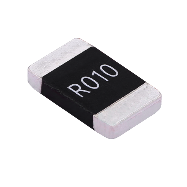
Key performance features: high power handling, ultra-low temperature drift, high overload withstand capability, low inductance at high frequency, and automotive-grade high reliability.
HoCG4527 Automotive Grade Molded Alloy Resistor
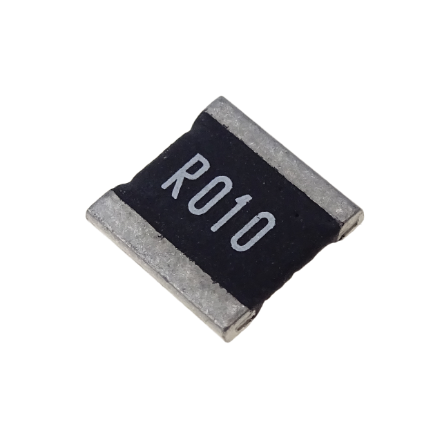
Key features: ultra-high current-carrying capability, ultra-high stability, ultra-low temperature drift, and low inductance at high frequency.
HoCG2728 Automotive Grade Molded Alloy Resistor

Alloy resistors, with their unique technical advantages—ultra-low resistance, low temperature drift, high power handling, low parasitic parameters, and strong pulse withstand capability—have become core components in current sensing, overload protection, and load matching circuits for EV charging stations.
Alloy Resistor Applications in New Energy