Application of alloy resistors in automotive EPS systems
author: Milliohm Electronics
2025-11-21

EPS (Electric Power Steering) is a core component of a car's steering system. Its core function is to provide auxiliary power through an electric motor and dynamically adjust the amount of assistance based on signals such as steering wheel angle and vehicle speed to achieve a steering experience that is "light and easy at low speeds and stable at high speeds".
I. Core Requirements of EPS and Compatibility with Alloy Resistors
The core components of EPS include a torque sensor (detecting steering force), an ECU (Electronic Control Unit), a power assist motor (providing power), and a reduction mechanism.
Its working logic is as follows: the torque sensor transmits the steering force signal to the ECU; the ECU calculates the target assist torque based on the vehicle speed, and then outputs the corresponding power by controlling the motor current. This process places extremely stringent requirements on current detection, thus necessitating high-quality sampling resistors:
High current and low power consumption balance: The operating current of the power steering motor is typically 5~50A, requiring a low-resistance resistor in series to reduce power consumption (avoiding heat generation that could affect system efficiency);
High detection accuracy: Current errors directly lead to insufficient or excessive power steering (e.g., an error >5% may cause abrupt steering feel), requiring resistor accuracy ≤±1% (±0.5% for high-precision scenarios);
Strong anti-interference and stability: The automotive environment presents high temperatures (engine compartment temperatures can reach over 85℃), vibration (continuous vibration during driving), and electromagnetic interference (EMI from the motor and wiring harness). Resistors must possess low temperature coefficients (to reduce temperature drift), high mechanical strength, and strong EMI resistance.
Alloy resistors, with their low resistance (0.1mΩ~10mΩ), high accuracy (±0.01%~±1%), low temperature coefficient (5~50ppm/℃), and high power density, perfectly match these requirements, making them the preferred component for EPS current detection.
II. Specific Applications of Alloy Resistors in EPS
① Closed-Loop Control of Assist Motor Current (Core Application):
The "assist accuracy" of an EPS depends on the precise control of the motor current by the ECU: the target assist torque has a linear relationship with the motor current (e.g., a 10A motor corresponds to 5N·m of assist). The ECU needs to obtain the actual motor current in real time, compare it with the target current, and adjust the output (PWM signal duty cycle) through an algorithm to achieve closed-loop control.
Detection Location: An alloy resistor is connected in series in the power supply circuit of the assist motor (usually the motor phase line or DC bus) to directly detect the motor's operating current.
Principle: Utilizing Ohm's Law (I=U/R), the resistance R of the alloy resistor is known and stable. By sampling the small voltage across the resistor (typically in the mV range, e.g., 5mV when a 5A current flows through a 1mΩ resistor), the ECU's AD module can calculate the real-time current, which serves as the feedback signal for closed-loop adjustment.
Advantages: Compared to Hall effect sensors, alloy resistors are lower in cost and have a faster response speed (no hysteresis effect, response time <1μs). Furthermore, in low-voltage (12V/24V), high-current scenarios for EPS, their detection accuracy is less affected by voltage fluctuations.
② Overcurrent/Short Circuit Protection (Safety Core)
If the motor or drive chip (such as MOSFET, IGBT) of the EPS malfunctions (e.g., motor stall, wiring harness short circuit), it will cause a sudden increase in current (potentially exceeding 100A instantaneously). If the power supply is not cut off in time, it will burn out components or even cause a fire.
Alloy resistors are the "first line of defense" for overcurrent protection. When the circuit current exceeds the safety threshold (e.g., set to 2-3 times the rated current), the voltage across the alloy resistor increases synchronously (e.g., when 100A flows through a 1mΩ resistor, the voltage reaches 100mV). The ECU quickly identifies the overcurrent signal through a hardware comparator or software algorithm, cutting off the motor drive signal within tens of microseconds, forcibly stopping the power assist output, and protecting the motor, drive chip, and wiring harness. Because alloy resistors have strong short-time overload capacity (able to withstand instantaneous impacts of several times the rated power), they will not be damaged immediately even during a short circuit, ensuring that the protection signal can be effectively captured.
③ Reverse EMF Suppression and Energy Recovery Assistance for the Motor
When the EPS motor returns to center, it generates a reverse EMF (generating state), which may cause a sudden rise in bus voltage (overvoltage), affecting the stability of the ECU's power supply. Some EPS systems use an "energy recovery circuit" to guide the reverse current into the battery. An alloy resistor can help monitor the magnitude and direction of the reverse current: when a reverse current is detected (identified by changes in voltage polarity), the ECU controls the freewheeling diode or MOSFET to turn on, returning energy to the battery. Simultaneously, the alloy resistor monitors the recharge current to prevent overcharging and battery damage.
III. Key Selection Considerations for Alloy Resistors in EPS Systems
EPS systems are often installed in confined spaces (mostly under the steering wheel or in the front compartment) and operate in harsh environments (high temperature, vibration, oil contamination). Therefore, the following parameters should be carefully considered when selecting alloy resistors:
① Resistance: Typically 0.1mΩ~5mΩ (too low a resistance will result in weak sampling voltage and susceptibility to electromagnetic interference; too high a resistance will increase power consumption; for example, 20A flowing through a 5mΩ resistor results in 2W of power consumption, requiring additional cooling);
② Power: Calculated based on peak current (P=I_{peak}²R), with a margin of 3~5 times (e.g., with a peak current of 50A and a resistance of 1mΩ, the peak power consumption is 2.5W, requiring a resistor of 10W or higher);
③ Temperature Coefficient (TC): Preferably ≤20ppm/℃ (e.g., manganese-copper alloy) to reduce resistance drift at high temperatures (engine compartment temperatures can fluctuate from -40℃ to 85℃; excessively high TC will increase detection errors);
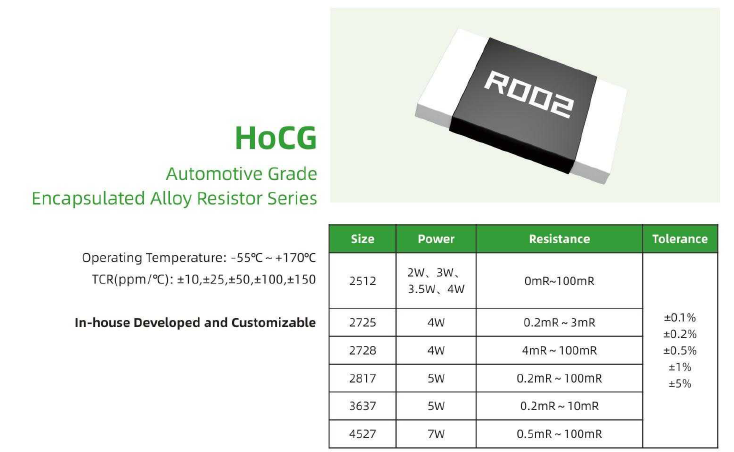
④ Packaging and reliability: Milliohm automotive-grade surface mount packages (such as 1206, 2512, 3920, 5930) or Kelvin four-pin Ho-VB series packages can be selected to adapt to compact spaces. At the same time, they must pass vibration (such as 10~2000Hz, 10g acceleration), temperature resistance (-40℃~150℃), and oil resistance tests to ensure long-term stability.


IV. Summary
In EPS (Electric Power Steering), the alloy resistor acts as the "nerve ending" of current detection. By accurately feeding back the motor current, it provides the core basis for closed-loop control of the ECU (Electronic Control Unit) and also undertakes the safety responsibility of overcurrent protection. Its low resistance reduces system power consumption, its high precision and low temperature coefficient ensure smooth steering feel, and its high reliability adapts to the harsh environment of automobiles. In short, the performance of the alloy resistor directly affects the control accuracy, safety, and lifespan of the EPS, making it an indispensable key component in modern automotive electric steering systems.
Note: If you would like to learn more about our products or solutions, or their application in specific scenarios, please feel free to contact our technical support.
Application principles and scenarios of aluminum-cased resistors
Application Principles and Scenarios of Alloy Resistors in On-Board Chargers (OBC)
Related Article
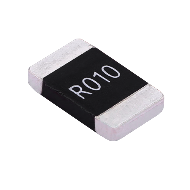
Key performance features: high power handling, ultra-low temperature drift, high overload withstand capability, low inductance at high frequency, and automotive-grade high reliability.
HoCG4527 Automotive Grade Molded Alloy Resistor
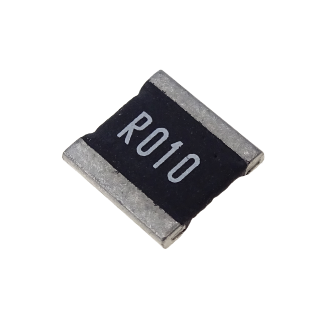
Key features: ultra-high current-carrying capability, ultra-high stability, ultra-low temperature drift, and low inductance at high frequency.
HoCG2728 Automotive Grade Molded Alloy Resistor

Alloy resistors, with their unique technical advantages—ultra-low resistance, low temperature drift, high power handling, low parasitic parameters, and strong pulse withstand capability—have become core components in current sensing, overload protection, and load matching circuits for EV charging stations.
Alloy Resistor Applications in New Energy